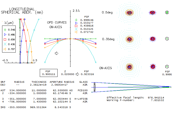
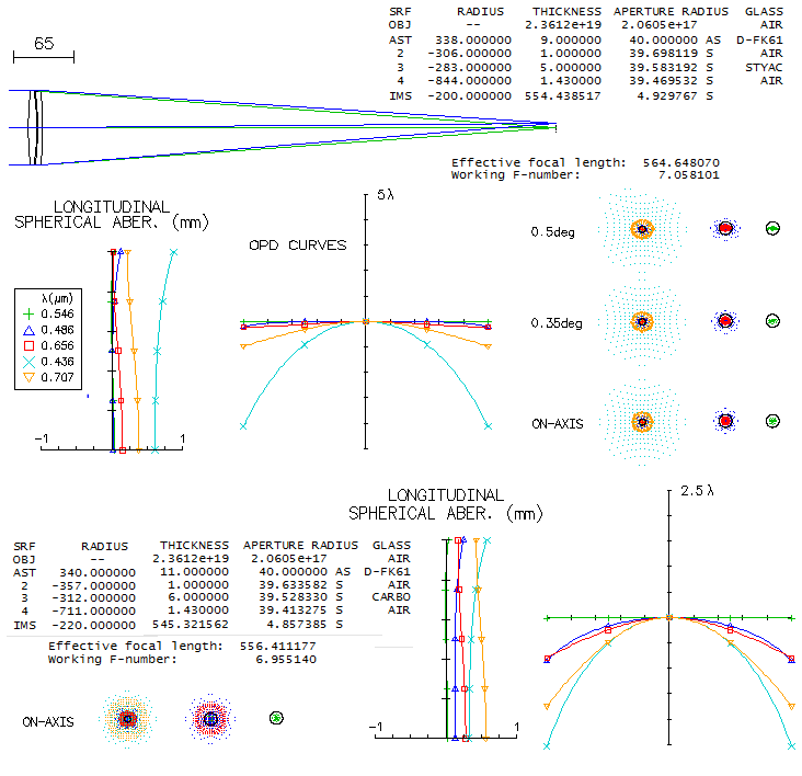
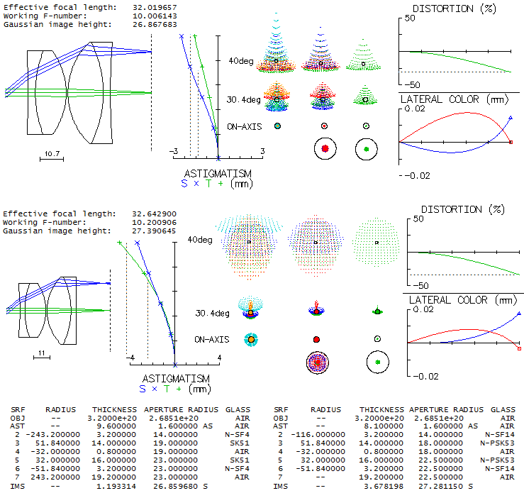
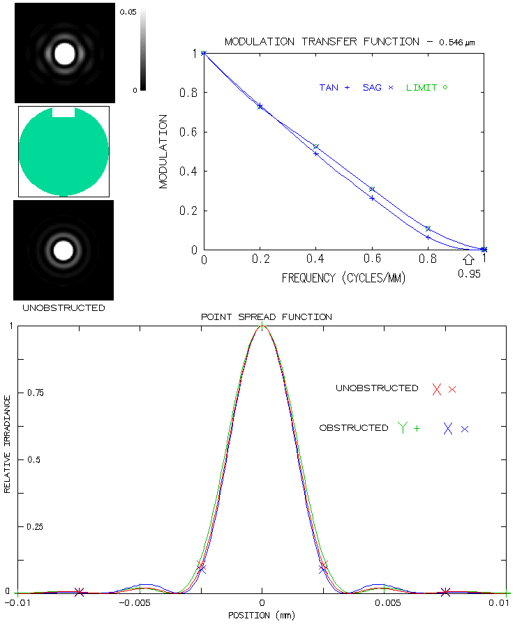
|
telescopeѲptics.net
▪
▪
▪
▪
▪▪▪▪
▪
▪
▪
▪
▪
▪
▪
▪
▪ CONTENTS ◄ 10.2.4.8. Houghton-Cassegrain comparison ▐ 12. THE EYEPIECE ► 11. MISCELLANEOUS TELESCOPE OPTICS
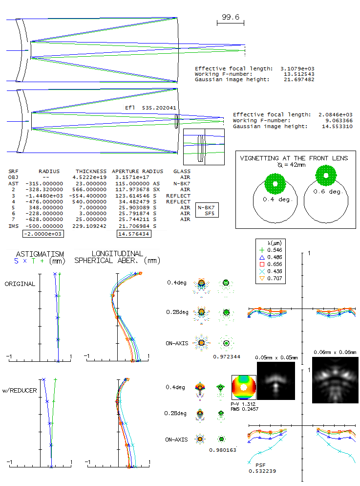
PAGE HIGLIGHTS 11.1 FOCAL EXTENDERS AND REDUCERSNearly as commonly used as eyepieces are the telescope accessories for extending, or for compressing the effective focal length - focal extender (also: Barlow, tele-extender), and focal reducer (telecompressor) lens. The former are used for adding more magnification options with a given set of eyepieces; also, extending/narrowing of the converging light cones improves eyepiece performance (not long ago, added benefit of a Barlow lens was extending tight eye relief of the conventional short-focus eyepieces, but that is less important with new generations of eyepieces with longer eye relief). Focal reducer lens, on the other side, can also serve the purpose of obtaining more magnification options, but is mainly interesting to those who want to make their systems "faster", particularly for astrophotography. For that reason, it is commonly made to acts as a field flattener as well. The two main parameters of either extender or reducer are its focal length and the inside separation from the original focus. In general, the larger either one, the larger the effect. Scheme below shows Barlow lens extending the original cone and, by the same factor M, multiplying the focal length and image magnification, i.e. L/L0=M. In the thin lens approximation, if the extended cone was the original one, and the lens was positive, twice stronger, the new focus would form where the dashed lines meet, with magnification.
Optically, the effect of either extender or reducer on the focal length, expressed as a magnification factor, is given with the same equation - it is only the sign of their focal length that produces magnification greater (extender), or smaller (reducer) than one. Graph below shows how system magnification changes with the focal length of the extender/reducer lens, with both lens-to-new-focus separation L and the lens focal length ƒ in units of the lens-to-original-focus separation L0. With the decrease in the relative focal length, extender lens' magnification asymptotically approaches infinity, and reducer lens' zero. Raytrace examples below illustrate some diverging-beam extenders.
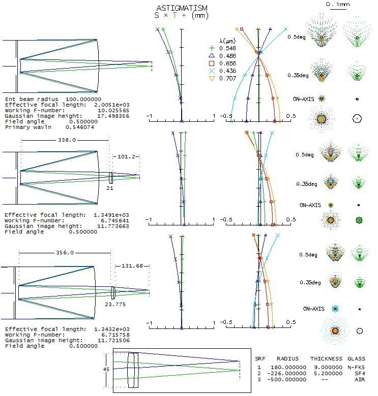
All are paired with a perfect 1000mm f.l. lens, so all aberrations are produced by the Barlows. Conventional Barlow lensConventional Barlow lens is a cemented doublet achromat, such as one given by Rutten/Venrooij (1, radii 799, -58, 48, spacing 8, 5mm), and has a moderate length and ray divergence, as long as its magnification factor doesn't significantly exceed 2. This particular Barlow lens was designed for the commercial f/10 Schmidt-Cassegrain, and has some residual negative coma, still negligible at f/8, but noticeable at f/5 (raytraced with OSLO "perfect lens", 100/800mm for f/8, and 160/800mm for f/5). Best image field is mildly curved, for all practical purposes good as flat. Bending lenses, these same glasses could produce a coma-free Barlow with more pronounced, but still acceptable field curvature, with less astigmatism and better chromatic correction (radii 122, -104, 32). Fancier glasses can produce somewhat better performance (2, radii 62.5, -49.05, -24.21, spacing 4, 2mm, 2x extender designed for the TAL-200K telescope), about half as long as the Rutten/Venrooij design, paid for with noticeably stronger divergence. Divergence is, expectedly, even stronger with TAL's 5x double doublet Barlow (3, radii inf, 19.41, 30.69, spacing 1.6, 3.2 and 2.2mm gap, as given in "New serial telescopes and accessories" by Y.A. Klevtsov, 2014, p172). The same angular field here is, of course, 2.5 times larger linearly than with 2x extender. Performance improves significantly for the same linear field, as the 0.1° spots show. Note that in the box at right is raytrace of a single doublet of this Barlow with 2x magnification at ƒ/8.
Finally, the "shorty" Barlow (4, radii 95.06, -39.17, -37.34, 30.14, spacing 7, 5, 3mm, from Smith/Ceragioly, Berry) unavoidably also has strong divergence. It has practicaly perfect correction over best image field, but its radius is potentially significantly curved. The astigmatic plot shows approx. 0.15mm defocus at 0.25° (about 7mm off axis in this case), which translates to -0.75 diopters field edge accommodation with the corresponding 14mm 50° FOV eyepiece, and nearly twice as much with a 7mm 100° FOV unit (negative sign indicates shifting focus right-to-left when light travels left-to-right; this is natural accommodation to a diverging beam, in this case the consequence of the edge field point being closer to the eyepiece, hence exiting eyepiece as a slightly diverging beam when the central point is in focus). Even -3 diopters with a 3.5mm 100° unit would be acceptable for most eyes (accommodating from infinity to 0.33m object distance). However, the field is not instantly accessible, as with a nearly flat field. It can be achieved by introducing astigmatism, which would require somewhat different glasses (e.g. SF10/N-FK5/N-LAF2, radii -6000, -38.8, -33, 55, spacing 7, 7, 3mm). Over the given field, there is no appreciable loss in the correction level, but unlike the zero-astigmatism design, "diffraction limited" over the entire usable (2" barrel limit) field at f/8, and nearly so at f/5, "diffraction-limited" field boundary with the flat-field design is at 0.36° radius at f/8, and 0.2° at f/5. Neither version is perfect close to the edge, but the zero-astigmatism type error can be remedied with accommodation, and astigmatism of the flat-field design can not. Probably the best design would have been in between, with somewhat weaker best image curvature and still negligible astigmatism (for instance, N-SF8/K10/N-LAF2, radii 244, -30, -27.4, 44mm, spacing 7, 5, 3mm). Note that the scale differs from one example to another; 1 and 3, and 2 and 4, are fairly comparable, while the former two are roughly 2-3 times larger vs. the other two than what it appears on the picture. Also, it should be noted that these outputs were produced with 1000mm f.l. perfect lens, and aperture diameter varying according to the relative aperture needed. If the focal ratio is given, change in aperture size will change field correction somewhat. Since the location of Barlow lens vs. original focus is constant for any given magnification, larger aperture, with larger focal length and image scale, will have converging cone for any given field angle hitting the Barlow lens higher, hence generating more of off-axis aberrations. Consequently, larger aperture will have correspondingly larger aberrations for any given field angle. However, they will remain practically unchanged for any given linear field. Telecentric Barlow lensMore recent development in both, focal extenders and reducers arena are the telecentric types. Unlike their conventional counterparts, they produce near-zero divergence exit beams. The advantage of it is that the added element doesn't affect - generally negatively - performance of telescope eyepieces, which are by default designed for near-telecentric (i.e. parallel with optical axis) entrance beams. For creating telecentric exit beams, a two lenses, or group of lenses opposite in their power sign, and with a wider separation, are needed. Two examples of telecentric Barlow below are, as before, with a perfect 1000mm f.l. lens, hence all aberrations come from the Barlow.
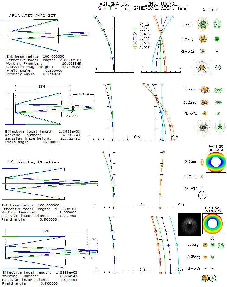
The first example is flat-field at ƒ/5, but developing some field curvature at ƒ/8. The other one, more compact, has nearly constant, strong field curvature (over 6 diopters, or approximately infinity-to-8 inch accommodation). However, even with zero accommodation, it is still comparable to the longer design (the reason is the very small relative aperture, below ƒ/22, hence fairly insensitive to defocus). In general, higher magnification requires longer units. Focal reducersThe simplest form of the focal reducer is a small achromat, usually cemented, corrected for infinity. Below is shown the effect of such random lens with a perfect 1000mm f.l. ƒ/10 perfect lens (top), a 100mm ƒ/10 doublet achromat (bottom left), and a 200mm ƒ/10 standard SCT. While its performance with a perfect lens is acceptable, it doesn't produce appreciable improvement with the SCT, as its original spots in the box show (the flat field SCT-alone spot is roughly 20% larger). Achromat's astigmatism actually enlarges the wavefront error, but what matters in the outer field is the angular size.
In the achromat, it significantly weakens field curvature, at a price of more astigmatism, mixed with some coma, in the outer field (in the box are the e-line spots for achromats best image field). Performance improves with dedicated achromatized lens pair, either cemented/contact or separated. An example of the former is given by Rutten and Venrooij, as a reducer/flattener for aplanatic (coma-free) SCT. It is shown below also with a perfect ƒ/10 1000mm f.l. lens, with which it does not produce flat field, since its astigmatism/field curvature needs to offset those of the SCT. As ray spot plots and diffraction images (polychromatic, for the wavelengths shown) show, gain over uncorrected flat-field performance is relatively small (in the box are shown flat-field and best image spots for the edge point w/o reducer).
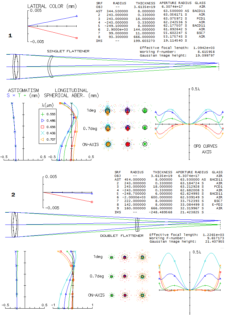
Three more examples include a simple reducer/flattener/coma corrector for the standard SCT (top), roughly similar in form reducer/flattener for an apo doublet, and a random 3-lens reducer with a 100mm ƒ/10 (1000mm f.l.) perfect lens. The SCT reducer produces off axis spots larger than the R&V cemented doublet, but its actual performance is significantly better. It is because a better part of its ray spot are widely scattered rays, due to significant proportion of higher-order aberrations curling up relatively small areas of the wavefront, as opposed to the compact astigmatic spots of the achromat (e.g. for given wavefront error, ray spot plot for primary spherical aberration is nearly 6 times larger than for the primary astigmatism spot). Better indicator of performance are the diffraction images, comparable in scale (important factor is that the air-spaced doublet, unlike the cemented one, also corrects for coma). Performance level of this reducer/corrector probably doesn't fall far behind some simpler commercial units, which perform acceptably up to about 1/3 of a degree field radius. More complex units use more lenses, usually 3 to 4, in any arrangement (e.g. Meade's 0.63x reducer consists of two cemented doublets, and its 0.33x reducer of three singlets), with the main difference being field definition beyond this circle.
The difference in flat-field performance is quite obvious in the case of the 80mm ƒ/8 fluorite doublet (middle). The reducer is telecentric, and unintended extra bonus was correcting the violet end. Finally,the 3-singlet reducer produces near-perfect 2-degree field with a perfect lens. Yet, its performance with systems having significant astigmatism/field curvature is uncertain. Next, an illustration of the performance level of the common f/6.3 SCT focal reducer/corrector. It is similar with both, Meade and Celestron, as well as some other makers, consisting of two cemented doublets. It is described as an accessory whose primary purpose is focal reduction, with unspecified corrective effect(s) other than it makes coma less visible. A number of different glasses can be used, so in the absence of any specific information except a published lens configuration for the Meade, designs presented here reflect what are the main properties of such a reducer, which should be roughly similar to the actual performance level (it is likely that different brands also have somewhat different design and output). It is assumed that the same two glasses are used for both doublets. Note that this replaces previous example, and is based on the actual location, back focus distance and linear (as opposed to angular) field radius of nearly half inch. The image is observed at the location of the base focus, or nearly so, which means that re-focusing by moving the primary closer to the secondary is applied in order to bring new focus to coincide with the standard one (change in output is negligible for focus shifts of up to a few mm, or so). It is likely that the reducer is near-optimized for the 8-inch SCT, which is shown below (top). Axial diffraction images are given for linear (top, same as the field edge images) and logarithmic response (bottom, to show it more clearly). Double doublet configuration can entirely correct for coma and astigmatism, but since the native astigmatism is of the opposite sign to the mirror Petzval curvature, it worsens best field curvature (middle). In order to maintain linear field size, angular field is increased to 0.67°. Consequently, field edge vignetting is about one magnitude, or 60%. The rear-end boundary is taken to be determined by the baffle tube inner diameter, equal to 37mm (shown as the vertical pink line right after the reducer's last surface). The top field edge diffraction images are as they would look like without vignetting at the rear end (note that the vertical elongation of the diffraction disc at the field edge is not due to astigmatism, but due to vignetting at the rear end effectively reshaping the aperture). Flat field blurs (left) are roughly comparable in size to the base SCT, possibly somewhat larger in their bright area; it's hard to tell since the blur doesn't entirely fit into the display window (note that the same linear size implies larger angular size in a faster system). Longitudinal shift of the astigmatic plots for different wavelengths is due to the longitudinal chromatism, with the plot origin by default being at the paraxial focus. This particular example has 0.52 reduction factor, but similar correction level - with the diffraction image enlarged according to the focal length - can be achieved at the 0.63 reduction (for instance, two N-FK5/F5 doublets, 200/-133/-333 and -1222/-133/-244mm radii). With the field curvature roughly at the level of the base SCT, coma can be significantly reduced, with astigmatism in a range from somewhat lower to somewhat higher. Levels of each can vary; the example shown (bottom) has little less than half the coma of the base SCT, and about 15% lower astigmatism (the latter results in a somewhat stronger best field curvature). As a result, best image field edge blur is noticeably smaller, while the flat field blurs are roughly comparable in size, but being more round with the reducer.
By adding astigmatism of opposite sign to that of the Petzval, a flat astigmatic field is possible, but the size of field edge blur does not change significantly (below). With this corrector coma is nearly 25% smaller than in the base SCT (surfaces contributing astigmatism also contribute coma), but astigmatism is five times larger in order for the best - median - astigmatic surface to be flat with the Petzval curvature over 50% stronger (keep in mind that the aberration coefficients express linear transverse aberration, hence the same value implies larger angular aberration in a faster system; similarly, the coma coefficient is over is 50% larger than that for astigmatism, but considering that for any given aberration magnitude transverse coma is 2.5 times larger than astigmatism, the latter is some 60% larger than coma as wavefront error). Blur size and shape can probably be changed somewhat in the final optimization, but with the given configuration no major improvements are possible. Main advantage of the curved field version is that the visual performance is noticeably better.
Reducer performance changes with the back focus, hence it will be different in SCT units of different size, and even of the same size but different back focus lengths. For instance, if the 0.63 reducer with curved field from above is placed in a C11 unit, which has significantly longer back focus than an 8-inch SCT, correction of the above 0.63 reducer is nearly perfect across best image surface; however, best image curvature is more than twice stronger than in the base SCT unit (below). The corresponding angular field radius for the base SCT is 0.25°, with the corresponding ray spot plots and diffraction images given for the best (top) and flat field (bottom). With the baffle tube inner diameter of 54mm the only vignetting at the rear end is by the reducer itself (assumed 48mm ID, probably a bit less in the actual unit). Note that the diffraction images are, for clarity, larger by a factor of 2 with respect to the 8-inch SCT. Best image diffraction patterns for both axis and field edge are given for linear and logarithmic response.
Here, due to the wider converging cones at the reducer, it does add some spherical aberration, lowering axial Strehl in the central line to 0.7 (undercorrection). Lenses do make Petzval curvature somewhat stronger, but the main factor is that they take out astigmatism of opposite sign to the Petzval, which increases field curvature as a price of coma/astigmatism correction. In general, any back focus extention through the reducer tends to reduce both, coma and astigmatism, but at the price of a stronger Petzval curvature. Finally, one more SCT reducer/corrector configuration, a 3-singlet arrangement used by Meade for its f/3.3 reducer. Shown is f/4.4 reducer using two common glasses, which fully corrects for coma while, similarly to the previous example, makes field curvature somewhat stronger. However, as the image is smaller, the curvature matters less.
Field curvature effect becomes significant only close to the field edge. This reducer would be primarily intended for photography, so its best curved field performance is irrelevant, but the simulations at the bottom illustrate modest effect of the quite strong field curvature (R=-144mm) on flat field performance (which would be still lower with the 0.33 reduction ratio). This reducer also induces spherical aberration (undercorrection) which is reduced if it is placed closer to the focal plane. That, however, tends to increase astigmatism, and make full correction of coma more difficult. As with the previous example, it is easier to make surface flatter with some residual coma left in, since the same surfaces that induce correcting (opposite) coma also induce astigmatism of the "wrong" sign. But, as this example illustrates, good performance is possible even with a strong field curvature. Actual units, being computer optimized, probably deliver still better performance. 11.2. DILWORTH RELAY TELESCOPEDon Dilworth's two mirror-relay telescope uses lenses to transfer an internal focus out to an accessible location. It could also be considered a two-mirror system with sub-aperture lens corrector(s), but the relay property makes these systems different from the rest. Unlike other two-mirror relay systems - notable example being Robert Sigler's design - which can have very good axial correction, but much left to be desired field wise (Sigler's 6-inch ƒ/7 system has coma close to that of an ƒ/4.5 paraboloid, and a horrendous field curvature of -44mm), Dilworth's design achieves both. It has an extraordinary monochromatic axial correction - practically zero aberration - weakly curved field, field aberrations lower than comparable aplanatic Cassegrain (Ritchey-Chretien), nearly 0.4 waves p-v of longitudinal chromatism in each, C and F line (comparable to a 100mm ƒ/30 achromat) and no detectable lateral color. 
Additional positives include relatively small central obstruction, fast focal ratio, and generous back focus. The negative is more complex alignment, and collimation sensitivity, due to the three widely separated lenses. However, with the relatively slow primary, it should not be significantly out of the ordinary. 11.3. SOLAR TELESCOPEMajority of the telescopes in use are those made for general astronomy. However, a telescope for general purpose may be limited in its ability to serve for some special purposes, such as observing outside of the visible range (infrared, radio), or observing particular astronomical object with special properties, such as the Sun. Among various specialized instruments for solar observations (coronagraph, spectroheliograph, etc.), probably the most interesting for an amateur is a telescope specialized for use of the H-α (hydrogen alpha) filter. Blocking the rest of abundant solar radiation makes possible observing of a variety of solar features, otherwise less pronounced or invisible (prominences, filaments, solar eruptions, etc.).
Solar H-α
etalon telescope
The H-α
solar telescope can either use H-α
filter placed in front of the objective, or H-a etalon placed inside
telescope, combined with a blocking filter in front of the objective
(for astrophotography of emission nebulae, such filter can be mounted
close to the image w/o use of blocking filter, but otherwise it is
avoided due to the heat-related risk). For the optimum
performance, such filter requires near-collimated
light, hence a telescope with H-α
etalon located behind the objective needs special arrangement providing
a collimated section within the light path. It can be created in a
simple arrangement of three singlet lenses, two positive and one
negative, as shown below.
The advantage of the etalon arrangement is that the filter can be
manipulated in order to increase, or modify performance. For instance,
double etalon will further narrow the passband;
tilting the etalon slightly shifts the
passband, allowing optimizing the passband to the detail of observation,
and so on.
This simple arrangement cancels all aberrations except field curvature
and some residual astigmatism
(chromatism, of course, is not corrected, but it is of no consequence
operating at a single spectral line). Despite the best field being
strongly curved, the 0.7-degree field is still well within diffraction
limited even at the edge, due to the small linear field extent.
Width of the collimated section is a
function of the front-to-mid lens separation: the smaller separation,
the smaller width, and vice versa. The flat-field correction somewhat
improves with the smaller separation, but not significantly. For any
given separation, the width of collimated section can be also widened by
using stronger glass for the mid element. It also improves field
correction but, again, only by 10-15%, or so.
The ethalon configuration can be used with an achromat as well.
The focal length of the negative front lens needs to be equal to its separation
from the original focal plane, and the positive rear lens needs to be slightly
weaker (depending on their separation). Best configuration here is
with the two lenses facing each other with their curved side. The aberrations
induced are a small amount of overcorrection, which actually improves correction in
the red, and field curvature. As an example, placing a negative plano-concave lens
lens (f=-291mm) at 800mm from the objective in a 150mm f/8 achromat, with the
plano-convex lens (f=304mm) 70mm behind it, induces slightly over 1/10 wave P-V
in the green e-line, with the error in the red r-line reduced to 1/30 wave.
No appreciable effect on chromatism and coma, but the best field curvature
goes from -460mm to -270mm.
In order to restore the proper horizontal orientation to the image, Amici prism
uses configuration with its back side split into two surfaces coming together
in the plane containing optical axis, and at 45 degrees with respect to it.
As a result, converging wavefronts containing this line are split in two,
with each portion being reflected to the opposite side, and after reflection
on that side merging together in the point image. If the prism is less than
perfectly symmetrical, these two parts of the wavefront will have different
optical path lengths, with the phase differential producing aberrated
diffraction images.
In addition, since a prism acts as a plane parallel plate, inducing longitudinal
chromatism, the color foci of the two wavefront portions won't coincide, which
can result in noticeable color infidelities. But this effect is generally smaller
and less important than the diffraction effect at the best focus. Images below are OSLO simulations of these diffraction effects, for two
simple scenarios: (1) even phase error between the two wavefront portions, caused
by one side of the prism being slightly longer, and (2) the error gradually
increasing away from the dividing line, as a consequence of one back side being at
a slightly different angle. The two parts of the wavefront have a constant
path difference. In this case, the part of the wavefront left of the
central line is delayed, i.e. having the longer path with respect to the other one.
Converging beam has a relative aperture of f/5, with the prism front side 100mm
in front of the original focus, and about 10mm wavefront diameter at the splitting
line. About 1/9 wave of spherical aberration induced by 50mm in-glass path is
present in all simulations.
The in glass differential δ produces optical path differential
(n-1) δ, where n is the glass refractive index (in this case
the glass is Schott BK7, with n=1.517 for the 546nm wavelength). The side length error is generally acceptable for δ~λ/4 and
smaller (corresponding to little over 1/8 wave of optical path differential).
It is still better than diffraction limited for twice as large error, but
doubling it again makes it unsuitable for higher magnifications (with the wavefront
diameter at the splitting line of 10mm, the width of the field affected
in the final image is nearly as much). At δ=1 and the wavefront split in two
halves, the resulting diffraction image is split in a double maxima (MTF graphs
below show the contrast consequence). In the second scenario, the path difference, i.e. wavefront error gradually
increases away from the split. The prism side angle deviation is 1/4, 1/2 and 1
arc minute (the actual error is somewhat larger, due to the longer path to the
opposite side). Since the wavefront becomes folded, resulting aberration has similarities
with astigmatism, particularly when the two wavefront portions are comparable in size.
For smaller prism errors, resulting wavefront errors are the
smallest for the wavefronts split in two, since they are positioned over the area
of lower deviation (that changes with the largest prism error, because large
wavefront errors result in a different, less predictable phase combining).
MTF graphs on the bottom shows contrast loss for the three patterns with the
largest prism error. The simulations suggest that the acceptable prism error of this kind
should be below 10 arc seconds. It is possible to correct
this kind of errors with phase coatings, but it would require
accurate measurement of the prism shape before it can be applied; in
other words, it would make it prohibitively expensive.
Another kind of diffraction artifact comes from the middle line where the
two double slanted sides meet. If it was near-perfect, with negligible width,
there would be no noticeable effect. If it is, instead, say, 0.05mm wide,
with the cone width at that location of, say, 10mm, it would be
effectively equaling a vane of 1/200 aperture width (e.g. 0.5mm
with 100mm aperture). With bright objects, it would cause a thin long spike
orthogonal in orientation to the prism's middle line.
When in a converging light cone, prism diagonal generates aberrations, both
chromatic and monochromatic. Since it acts like plane parallel plate,
Eq.105.1 applies, with d/L becoming 1/2F, F being the focal ratio
(f/D, focal length by aperture diameter). Since d/L becomes a constant
for any given system, prism distance, i.e. beam diameter on its
front surface becomes non-factor, with the only remaining factors
being the focal ratio, in-glass path (thickness) and glass refractive
index. Taking for the index n~1.5, gives for the only two possibly significant
monochromatic aberrations the P-V wavefront error (mm) as W=T/1380F4
(spherical aberration) and W=T/65F3 (coma). Graph below
shows how they change as a function of focal ratio (F).
Spherical aberration and coma affect all wavelengths neary equally,
which makes them a part of chromatic error as well. Purely chromatic
errors are longitudinal chromatism, caused by the change in refraction
with the wavelength, and lateral color, which is generally negligible.
Picture below illustrates these aberrations on a 32x32m prism (BK7) in
f/10 and f/5 cone. The objective is a "perfect lens", so all
aberrations come from the prism. Note that different prism types have different
in-glass path length: for a given clear opening, Amici prism has it about
60%, and penta prism 3.4 times longer than the standard 90-degree prism.
At f/10, Zernike term for primary spherical aberration (8) is 0.002853,
which divided with 50.5 gives
the RMS wavefront error as 0.001276. The corresponding P-V error is
larger by a factor 11.250.5, or 1/234 wave (both in units of 546nm
wavelength). It, expectedly, agrees with the equation, since no other
significant aberrations are present. The term for coma (4) is 0.003984,
which divided by 80.5 gives the RMS error as 0.00141 (the
P-V error is larger by a factor 320.5). So, at
f/10 coma is somewhat larger than spherical aberration, but both are
entirely negligible.
Longitudinal chromatism has a form of reversed primary chromatism, with longer
wavelengths focusing shorter than shorter wavelengths (the consequence
of the refraction at the front surface being diverging).
It is a consequence of image displacement caused
by the cone angle narrowing inside the prism (looking at the raytrace
side view, it is causing the oblique line sections to become longer).
The displacement is given by (1-1/n)T, and the variation in n (δn)
with the wavelength produces longitudinal chromatism, given by (T/n2)δn.
It remains nominally unchanged with any focal ratio (of course, due to the
smaller Airy disc at the faster focal ratio, chromatic error increases
correspondingly). At f/5, the error in both, F and C line is over 0.4 wave
P-V. It will change relatively little in a fast achromat, unless a very small,
but it would introduce noticeable color error in the reflecting systems, or
any other fast systems with a very low level of chromatism.
Misaligned prism will induce all-field coma, astigmatism and lateral
color. Coma dominates astigmatism at fast focal ratios, while the latter
can be larger at ~f/10 and slower. At f/5, 1-degree prism tilt vs.
optical axis will induce 0.023 wave RMS of coma, and 0.0068 wave RMS
of astigmatism. Since coma changes with the 3rd power of focal ratio, and
astigmatism with the 2nd, at f/10 coma drops to 0.0028, and astigmatism
to 0.0017 waves RMS. But with the coma changing with the tilt angle,
and astigmatism with the square of it, at 2-degree tilt the latter will
be slightly larger. Since the magnitude of tilt -induced aberrations can be significant
only at fast focal ratios - except at insanely large tilt angles - it
is only coma that could be of concern.
Tilt-induced lateral color (prism effect) doesn't change nominally with the focal ratio, but its
magnitude vs. Airy disc does, in proportion to it. At f/5 and 1-degree
tilt, the mid-field separation of the F and C lines is 0.002mm, or about 30%
of the Airy disc diameter. For the field center, the separation shouldn't
be larger than half the Airy disc diameter. Since it increases with the
tilt anlgle, it should stay below 2 degrees. At f/10, 1-degree tilt will
induce only half the error at f/5, i.e. the F and C lines separation
will be about 15% of the Airy disc diameter.
The standard 4-vane spider is the simplest form of the kind, but
rotational stability is not its strongest point. To improve on that,
the vanes need to be rearranged, breaking the symmetry of a cross.
Simulations below show diffraction effect of two of such arrangements
vs. standard 4-vane form.
Due to the different converging angles from the vane sections,
the modified spider produces wider, complex spikes of similar length. While the
amount of energy transfered out of the Airy disc depends solely
on the vane face area, significantly wider spikes could appear either
more, or less pronounced, depending on the detector's filtering.
The eye could be biased toward wider, fainter spikes, or toward
narower, brighter ones (for identical vane area). Which it is, has
to be established experimentally; it is quite possible that it could
vary individually. A variation of the middle vane arrangement,
used on some commercial telescopes lately, have the vanes
shifted off only slightly, so that their sides lie on a
common strait line splitting the aperture in half (below).
Diffraction images show similar doubled spikes, but with one clearly
dominant. Since the spike energy is nearly identical with that of the
standard cross arrangement, spikes should be a bit less pronounced
visually, with the faint spike likely remaining invisible (note
that these patterns are brighter due to 2.5 times lower normalization
value for the unit intensity, 0.02).
Doubling the vanes to increase spider rigidity will also alter their
diffraction effect. The reason is diffraction interference between the
vanes. As the simulation below shows, the spike of a doubled vane is
broken into bright segments and extended vs. single vane pattern.
The consequence is slightly more energy transferred to the outer areas,
even if the vane area is kept unchanged (graph on the right is effectively
magnified by showing 5 times smaller radius on the same frame size).
On the doubled area vanes' pattern
(right) can be detected presence of secondary side maximas, which would
imply less energy in the principal maxima, i.e. main spike. As with
the vane configurations above, whether the eye would be more sensitive to a
longer, segmented, and slightly less bright spike, only experimental
examination will answer.
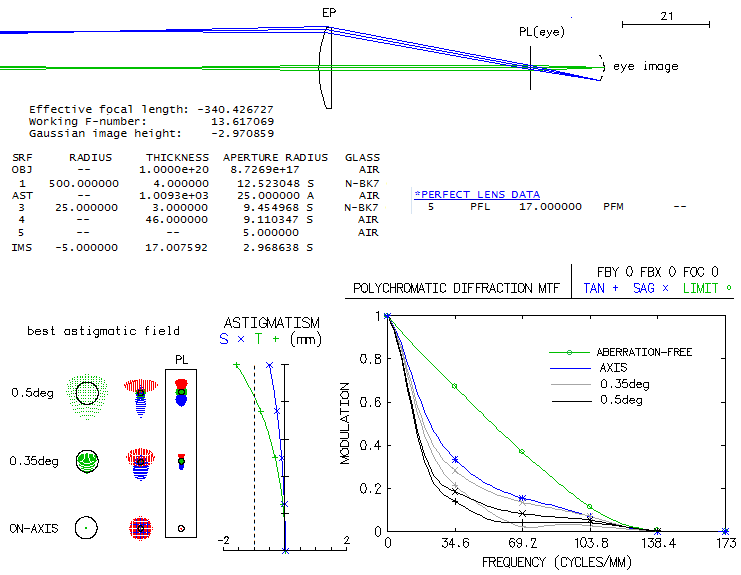
Eyepiece performance level is commonly determined by reverse raytracing,
i.e. in a setup when the eyepiece exit pupil becomes aperture,
and collimated light pencils passing through it travel through the
the eyepiece in reverse, to form an image in front of the field lens,
at the nearly same location where forms the image of the objective.
Image formed by raytracing eyepiece in this manner is real image,
but it is neither image that a perfect lens would form if placed
at the eyepiece exit pupil, nor image of the objective. Rather, it
is an image at the location of objective's image that would produce
perfectly collimated pencils at the exit pupil end. As such, this
image reflects aberrations of the eyepiece in their kind and magnitude,
some of them reversed in sign, some not. For example, if reversed raytracing
produces field curvature concave toward eyepiece, it implies that
such curvature would produce perfectly collimated exit pencils because
eyepiece itself generates curvature of opposite sign (it seems illogical
since the two curvatures seemingly coincide, but the image space of the
eyepiece is behind the eye lens, not in the objectve's image space; hence
with a flat objective's image the eyepiece would produce exit pencils becoming
converging toward outer field - because the field points in the image of the
objective would've been farther away than what it needs to form a collimated
beam - i.e. would form a curved best image surface
of the opposite sign). On the other hand, if
reverse raytracing produces overcorrection, this means that the eyepiece
would, with zero spherical aberration from the objective, form exit pencils
with rays becoming divergent toward pencil edge (since off-axis points on unaberrated
image surface are in this case closer to the eyepiece), focusing
farther than rays closer to the center, i.e. also generating overcorrection.
As long as the geometry of pencils passing through the exit pupil
is identical, so will be the aberrations generated. But this is
strictly valid only for points close to axis. The farther off
field point, the more likely that the perfect exit pencils that we
are starting with in reverse
raytracing won't exactly match those generated by a perfect input
from the opposite end, and that will
cause different aberration output as well, possibly significant.
One particular difference is that reverse raytracing can be done
from one fixed pupil location at a time. It is generally insignificant
with eyepieces having relatively small exit pupil shift with the change
of field angle (so called spherical aberration of the exit pupil,
with the pupil generally shifting closer toward eye lens with the
increase in field angle), but when it's significant, raytracing from
any fixed pupil location will cause gross distortion of the astigmatic
field for field zones with different exit pupil location. The only way
around it is to raytrace for several different exit pupil locations, and
piece up the actual field from that. This problem vanishes in direct raytracing,
where every point's cone simply goes to its actual exit pupil.
To make easier to detect the differences, a wide field eyepiece is
needed, and for the ease of accessing its optical process it should
be simple as possible. The perfect candidate is a modified 1+1+2
Bertele, which is for this purpose designed to produce 80°
apparent field of view (AFOV). While not in the league of the
(much) more complex designes for this field size, it is still
significantly better than other conventional designs. Below is
how it raytraces in reverse, and directly, the latter using
OSLO "perfect lens" as the objective and at the eye end. Eyepiece
focal length is 10mm, and exit pupil diameter is 1mm, hence it
processes f/10 beam.
Top half shows reverse raytracing. Surface #1 is the aperture stop,
and #9 the image. The section between two marginal cones
(6.4mm radius) is the actual image, and
the full length of the vertical dashed line (8.4mm radius) is Gaussian image,
i.e. image that would've been seen w/o distortion at the entry
field angle (in effect, the image seen at that angle from the distance
equal to the eyepiece focal length, as illustrated with the dotted
lines at left). Column of numbers at right are the heights of the marginal chief
ray (central ray) at all surfaces. Astigmatism plot shows reversal of
the tangential line (in the plane containing axis and chief ray) toward
field edge, preventing further increase in the outer 20%, or so, of the
field radius. At 40° off, the P-V wavefront error is 2 waves. Note that due
to the exit pupil shift (3.7mm eye relief for 40° to 5.5mm for
half-field), tangential line for 3.7mm pupil position slightly magnifies
the longitudinaludinal aberration for the upper half of the field;
the actual line is a bit flatter over that section. As the wavefront map shows,
on its way through the lenses the wavefront acquires vertical elongation,
despite it being cut into a horizontal ellipse (0.5x0.383mm) at the
aperture stop (OSLO Edu doesn't have pupil-that-tilts-with-field-angle feature).
Longitudinal aberration plot shows entirely negligible spherical
aberration, and not entirely negligible axial chromatism. Defocus δ in the
blue F line of less than 0.1mm indicates ~0.2 waves P-V wavefront error
at f/10 (for 486nm wavelength, from δ/8F2), and four times
as much at f/5. Error in the violet g-line is three times larger. lateral
color is well controlled accross the field, with the F-to-C separation
reaching half the Airy disc diameter at the field edge.
Bottom half shows direct raytrace of the same eyepiece with a "perfect
lens" as the 89.4mm f/10 objective (the focal length is determined from
the field-end angle of the marginal chief ray in reversed raytracing).
Focal length of the "perfect lens" at the image end is set to 10mm,
to produce a directly comparable f/10 system. Longitudinal chromatism
and spherical aberration are nearly identical to those in reversed raytracing.
But that is where the similarity ends.
Here, Gaussian image is smaller than the actual, apparent one, as a result of the
positive (pincushion) distortion, nominally the inverse of the
negative distortion in the reversed raytracing (1.32 vs. 0.76).
As a result of positive distortion, with the edge cone
visibly more elongated, the Airy disc at 40° is noticeably
larger than on axis, unlike the reversed tracing, where it is smaller.
Longitudinal astigmatism at 40° is about doubled, but
the P-V error is smaller: 1.8 wave. This is mainly the result of
the effective f-ratio for that cone being f/13.2, with the
transverse astigmatism smaller by a factor 1.75 vs. f/10,
and more so vs. effective focal ratio at this field point in the
reverse raytracing. Tangential curve now extends farther out, as a
result of the higher order astigmatism now being of the same sign
as the primary, adding to it instead of taking away as in reverse
raytracing. This is caused by the narrower cone of light passing
through the eyepiece for the outer field points, which much
more affects secondary astigmatism, changing with the 4th power of
cone width
(as opposed to the 2nd power with primary astigmatism),
with the 40° pencil not quite filling out the exit pupil circle
outlined by the axial cone, as it does in reverse raytracing.
As a result
of the different astigmatism plot, field curvature also changes:
instead of zero accommodation at the edge, and +1 diopter required
for 0.7 field radius, now edge requires somewhat over +1 diopter,
and the 0.7 field radius is flat, requiring zero accommodation
(small box bottom right, accounting for the effective 13.2mm focal
length of the perfect lens at this point). However, it should be noted
that if the two astigmatism plots would be corrected for the distortion
effect, they would become very similar, despite the difference
in the sign of secondary astigmatism.
Unlike the 40° wavefront in the reverse raytracing, elongated
vertically, here it's flattened, and noticeably more so. This is
caused by refraction at large angles, compressing or expanding wavefront
vertically, and shows the true extent of it
(the elongation in reverse raytracing is partly offset by the
horizontally elliptical wavefront outline determined at the entrance pupil).
This asymmetrical astigmatic shape will result in asymmetry of both,
ray spot plots and diffraction images along the extent of longitudinal
aberration. Here, the tangential line, laying in the sagittal plane, is
noticeably thicker, because it's formed by the (shorter) vertical
wavefront sections focusing into it (blue on the wavefront map is
its delayed area, hence it forms convex surface focusing farther away),
as well as about 50% longer, since
the wavefront extends that much more horizontally. As a result,
best focus is not in the middle between sagittal and tangential focus,
but closer to the sagittal line, which is
laying in the tangential plane (the one containing axis and the chief ray),
as indicated on the astigmatism plot.
Overall, the differences in aberrations magnitude are small, but one
needs to keep in mind that some of them do reverse in sign with the
change in light direction.
For instance, nominal lateral color error is reversed,
and roughly doubled, but the actual change is relatively small
due to the larger Airy disc (it is similar with astigmatism,
with the two plots appearing grossly different, but with the
actual P-V error diferential being near negligible).
Polychromatic Strehl for telescopes with refracting elements
is commonly given for photopic (daylight)
eye sensitivity. Strictly talking, it is valid only for daytime
telescope use, but both sides of the market seem to be neglecting it,
or simply are unaware of it. Since the Strehl figure is used as a
qualifier of the level of optical quality - 0.80 for so called
"diffractin limited", and 0.95 for "sensibly perfect", it does
matter to know that it is limited to the sensibility mode used for
calculating the Strehl. In general, due to the higher overall sensitivity
in the mesopic mode - and particularly toward blue/violet -
and the error usually being greater in the blue/violet, the mesopic
(twilight level) Strehl will be lower than photopic (broad daylight).
It likely worsens somewhat toward scotopic (night conditions) mode,
but telescopic eye is most likely to be within the range of mesopic
sensitivity. How significant is the difference between photopic and
mesopic Strehl depends primarily on the magnitude of chromatic error
in the red and blue/violet, with the latter being more significant
since, unlike the blue/violet, sensitivity to the red generally declines toward mesopic and
scotopic mode. While these eye sensitivity modes are relevant for
visual observing, for CCD work it is the chip sensitivity that needs
to be used for obtaining the relevant, CCD Strehl. Here, CCD
sensitivity is a rough average of the range of sensitivities of
different chips.
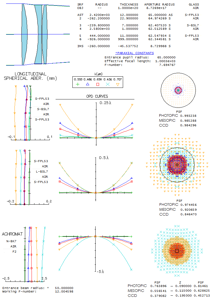
As illustration of the difference between Strehl values for
photopic, mesopic and CCD Strehl, it will be calculated for a
highly corrected TOA-like triplet in two slightly different
arrangement: one with the standard Ohara crown, S-BSL7, and
the other with its low-melting-temperature form, L-BSL-7. Slight
difference in dispersion between the two is sufficient to
produce larger axial error, particularly in the red and violet,
which will show the difference in correction level between two
seemingly highly corrected "sensibly perfect" systems, when judged by the photopic
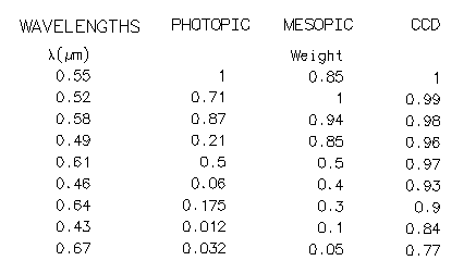
Strehl value alone. Strehl values are calculated using 9
wavelengths spanning the visual range, as shown below. Mesopic
sensitivity is approximation based on empirical results, somewhat
different from the official mesopic sensitivity, which is merely
a numerical midway between photopic and scotopic values.
From top down, first shown is a lens using S-BSL7, extremely
well corrected for axial chromatism. So much so, that the mesopic
Strehl, and even CCD Strehl are only slightly lower. This lens
practically has zero chromatism in the violet, a rarity indeed.
Replacing S-BSL7 with L-BSL7 (same prescription, except slightly
stronger R1 - 2380mm - to optimize red and blue) roughly doubles axial chromatism,
except for the violet, which is now at the same level as the
deeper red. Photopic Strehl is still excellent, suggesting there
is no noticeable difference in the chromatic correction between the two.
However, mesopic Strehl tells different story: this lens is not
"sensibly perfect", and its CCD Strehl sinks toward 0.80.
Mesopic Strehl gives different picture for achromats too. According
to its photopic Strehl, a 100mm
f/12 achromat is slightly better than the "diffraction limited"
at its best diffraction focus
(0.09mm from the e-line focus toward the red/blue; first column
shows Strehl values at the best green focus). But its mesopic
Strehl, also at the best diffraction focus, is only 0.63, and its
CCD Strehl dives down to 0.45. Knowing that the Strehl number reflects
average contrast loss over the range of MTF frequencies (for the
mesopic Strehl it is, for instance, 37%), implies that this achromat
is nowhere close to "diffraction limited" under average night-time
conditions. For that, it needs to be twice as slow, f/24.
In conclusion, it is hard to draw a precise line for where a
"sensibly perfect" photopic Strehl should be for telescopes used at night,
but it seems safe
to say that it does need
to be significantly better than 0.95; probably close to 0.99.
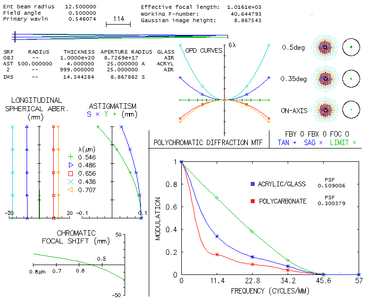
Optical plastics are widely used for production of small and not so
small lenses for all kinds of cameras, glasses and optical devices,
but rarely for telescopes, and when used, nearly without exception for those of
low quality. Most important optical plastics are acrylics, polycarbonates
and polystyrenes, but some other are also viable. Optically, they
can be as good as glass, but have several times higher thermal expansion,
and a 100-fold higher variation of the refractive index with temperature.
Also, they are more prone to static charges, and more difficult for coatings.
On the good side, they are ligther, safer, and cheaper. Technological advances
resulted in a wider number of optical-grade plastics available, which
makes their application for small telescope objectives easier. Follows
overview of the performance level of optical plastics - mainly those listed in OSLO Edu catalog -
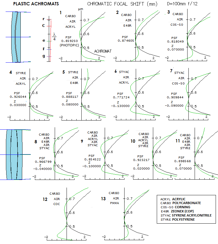
as components of achromatic 100mm f/12 doublets and triplets. In general, they
have better color correction, occasionally approaching - even exceeding -
the minimum "true apo" requirement of 0.95 Strehl.
Doublets are of the Steinheil type, with the negative element in front, because
the "flint" element in most of objectives, polycarbonate, is more resistant to
impact and temperature (in general, order of elements does not significantly
change the output). Performance level is illustrated with a chromatic Focal
shift graph, against that for the standard glass achromat (BK7/F2, black plot).
Chromatic focal shift shows the paraxial focus deviation for other wavelengths
vs. optimized wavelength (546nm, e-line). In the absence of
significant spherochromatism - which is here generally the case -
it is a good indicator of the level of longitudinal chromatic correction.
The P-V error of defocus can be found from the graph for any wavelength,
using P-V=δ/8F2, where δ is the focus
shift from the e-line focus (0 on the graph) and F is the focal number.
Graphs are accompanied with the corresponding photopic Strehl (25 wavelengths, 440-680nm),
except for the last two, whose rear element plastics are not listed in OSLO (direct
indexing for five wavelength was entered from ATMOS). The Strehl value
is for the diffraction focus, which for most of these objectives
does not coincide with the e-line focus (amount of defocus is given
as z, and can be positive or negative, depending on the
plot shape).
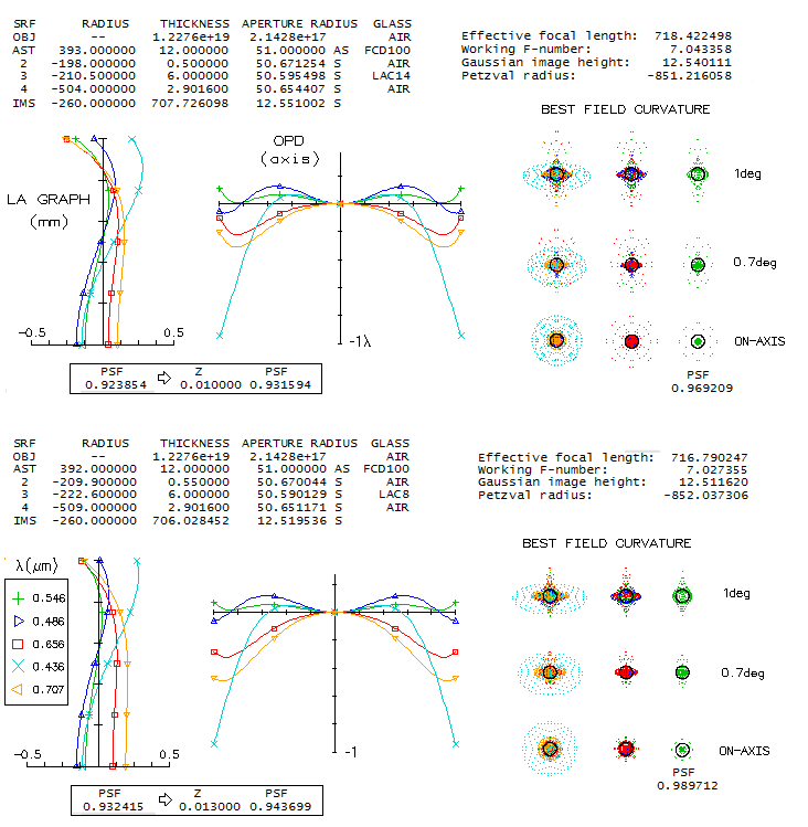
All but one plastic lens combination have a higher Strehl than the glass achromat
(0.81). Some combinations have near-apo correction in the blue/violet,
some in the red, but most important is how well corrected is the 0.5
to 0.6 micron section (approximately). Two doublets have Strehl value exceeding 0.9, as well as
two triplets, with one of them qualifying as a "true apo" by the
poly-Strehl criterion of 0.95 or better (#8).
It wouldn't satisfy the P-V apo criterion having 2.3 wave error
in the violet g-line (1/6 wave F-line, 1/5 wave C, and 1/2.5 wave r-line)
but due to the very low eye sensitivity to it in the photopic mode,
it has little effect on the photopic Strehl. The more appropriate for
night time use, mesopic Strehl, would be somewhat inferior to
objectives with a similar photopic Strehl, but better violet correction.
There are other plastics available, and more combinations possible (also,
the properties of any given plastic can vary somewhat depending on its
production process), but
these shown here suffice to conclude that optical-grade plastics
can be superior to the standard glasses in chromatic correction.
Some could even produce the "true apo" level in the range of mid
to moderately long focal ratios.
The older generation of extra-low dispersion glassess, with Abbe number
around 81, is commonly considered inferior in their performance limit to
the latest generation, with Abbe number around 95 (also called
super-low dispersion, or SD glasses). However, the larger
Abbe number gives one single advantage: with any given mating glass
the higher order spherical aberration residual is lower, allowing for
somewhat faster lens for a given design limit in the optimized
wavelength. But the difference is generally small. Let's illustrate this
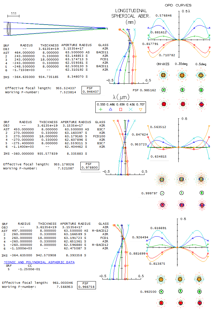
with Hoya's FCD1 and FCD100 glasses in a 5-inch f/7.5 triplet objective.
Limiting the mating glass to Hoya's catalog, the best match for FCD1 is
BCD11, and for FCD100 BSC7 (Hoya's equivalent of Schott BK7). As image
below shows, a 5" f/7.5 triplet with FCD1 (top) has photopic polychromatic
Strehl rounding off to "sensibly perfect" 0.95 (mesopic value would be somewhat
lower, but not by much, considering relatively low errors across well
balanced spectrum). The FCD100 triplet (middle) does have better polychromatic
Strehl - rounding off to 0.98 - but about half of the differencial comes
from the optimized line correction. Since the limit in the optimized e-line
for the FCD1 triplet is at the level of 1/15 wave P-V of primary spherical
aberration, the actual units with a similar optimized line correction
would have no perceptible difference in color correction (granted,
any given optimized line correction level would be easier to achieves
in the FCD100 triplet, due to its more relaxed inner radii). Note that
the FCD1 triplet correction mode minimizes the error in the violet g-line,
which is not the best general correction mode. With slightly less
of the positive power, the error in violet would increase, but would
decrease in the other three wavelengths, with the F and C nearly touching
at the edge zone on the OPD graph. In such case, the FCD1 poly-Strehl
increases to 0.966 which, considering the unequal error in the
optimized line, would imply the same level of chromatic correction.
It is obvious on the LA graph that the FCD1 triplet has significantly
higher spherochromatism on the primary spherical level, most of it the
result of more strongly curved inner radii. But the sign of higher order
spherical residual - after optimally balancing the optimized wavelength -
significantly reduces the aberration in the blue/violet, while
increasing it only moderately on the red end. As a result, Strehl values
for non-optimized wavelengths are generally close to those of the FCD100
triplet.
One other possibility is using moldable glasses. Best match for FCD1
is M-BACD12. If one surface is aspherized, all four inner radii can
be equal, and the triplet is nearly as well corrected as the one with
FCD100 glass (bottom).
In all, how objective performs still depends more on the combination,
than any single glass. It is possible that the older ED glass objective
even performs better, although it is generally to expect small to
negligible advantage with the higher Abbe# varieties. The difference
is more pronounced in the doublets, because the higher order residual
increases exponentially with the lens curvature, and doublets require
them significantly stronger than triplets.
While not common, use of microscope eyepieces in telescopes
does happen. How well these eyepieces can be expect to perform?
Is a good name on them implying they will be as good as those
made for telescopes, or even better? The answers are: "no one can
tell", and "no", respectively. There are two main differences
between the standard microscope and a telescope with respect to
the eyepiece performance: (1) due to the significantly shorter
objective-to-image distance - for a standard old-fashioned microscope
the main part of it the so called "optical tube length" (OTL), standardized
to 160mm - rays entering any given eyepiece field stop have
significantly larger divergence, and (2) due to the very small objective,
the effective focal ratio is very high (measured as a ratio of objective
diameter vs. objective-to-image separation; not to confuse with the
microscope numerical aperture, which is measured vs. objective-to-object
separation). The former generally increases off axis aberrations,
while the latter makes them smaller. In other words, looking only
at #1, eyepiece optimized for a microscope would have to be sub-optimized
for a telescope with respect to field correction. How much does #2
offset for this?
Since the microscope magnification can also be expressed as a product
of the objective and eyepiece magnifications - the former given by OTL/fo,
and the latter by 250/fe, with fo and
fe being the objective and eyepiece focal length,
respectively - we'll illustrate the divergence vs. focal ratio offset
with an average objective of 10mm focal length, and a 20mm focal length
Huygenian eyepiece (from the above, they produce 160x250/10x20=200
magnification). Image below shows the optical scheme of a microscope
(top) and an actual raytraced system with the given parameters (bottom).
The objective and eye lens in the latter are "perfect lens", so neither contributes
aberrations (note that the correct magnification for perfect lens 1
should be -16.13, but makes no difference in the ray spot plot).
The eyepiece is upscaled 10mm Huygenian shown under "Individual
eyepieces" on eyepiece raytracing page, so its nominal
aberrations in a telescope are twice larger than those shown for the 10mm unit.
In this microscope setting, the 20mm unit (due to re-orienting its effective
focal length is around 22mm) shows entirely negligible
aberrations all the way up to its 10mm radius field stop. The effect
of the f/86 cone (the paraxial data given below objective is for the objective only)
makes the effect of significantly stronger divergence entirely
negligible over the strongly curved best image field (-4.5 diopters
of accommodation required at the edge). Even over flat field, it dwarfs
defocus effect to 1/12 wave P-V at the field edge. Note that the field
is given in terms of object height, with 0.618mm corresponding to
25° apparent FOV in the eyepiece, and 3.33° true field of
the objective, i.e. angular radius of the object (magnification is not, as with
a telescope, related to the angular size of the object in the system,
but to its angular size as seen from the standard least distance of distinct vision,
250mm; on the schematic microscope, that angle magnified by the objective is
α0, and the final angular object radius is α).
In all, correction requirements for microscope eyepieces are much lower
than those used in telescopes. This applies to both, axial and off-axis
correction, and that is the main risk in using microscope eyepieces for
telescopes: those
performing just fine in a microscope, could become sub-standard in a
telescope. Another possible obstacle, not visible in this demonstration,
is that microscope eyepieces could be optimized to offset typical
aberrations of microscope objectives, while telescope eyepieces are
generally designed to produce best possible stand-alone image.
While looking for some modern, "extremely achromatic" camera prescription,
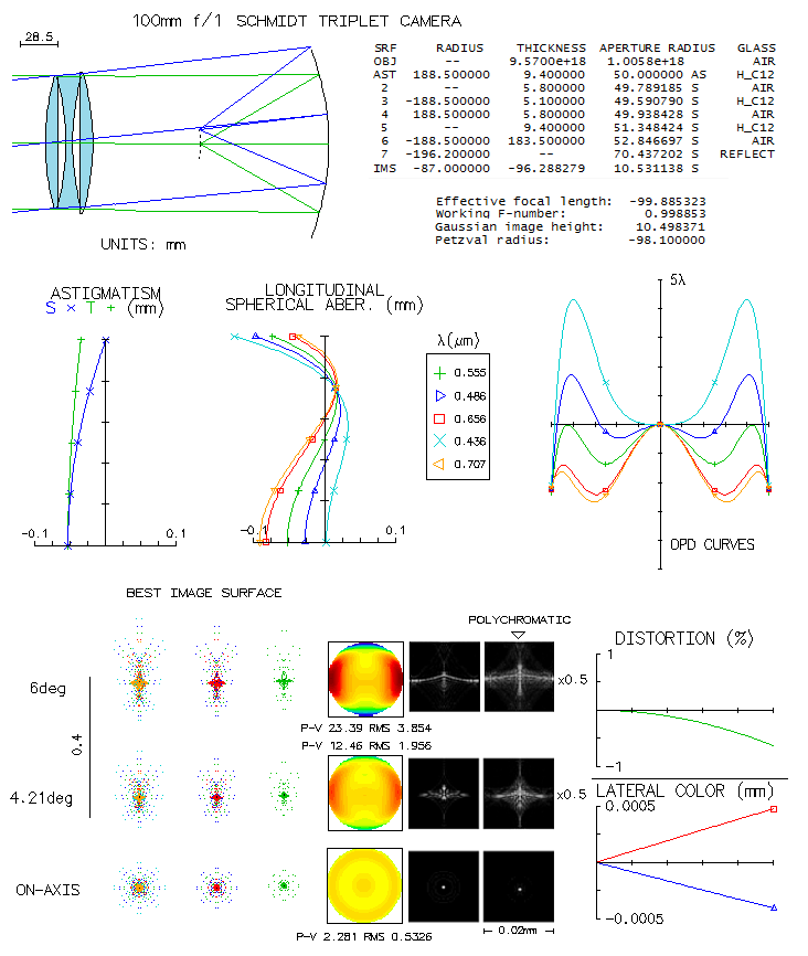
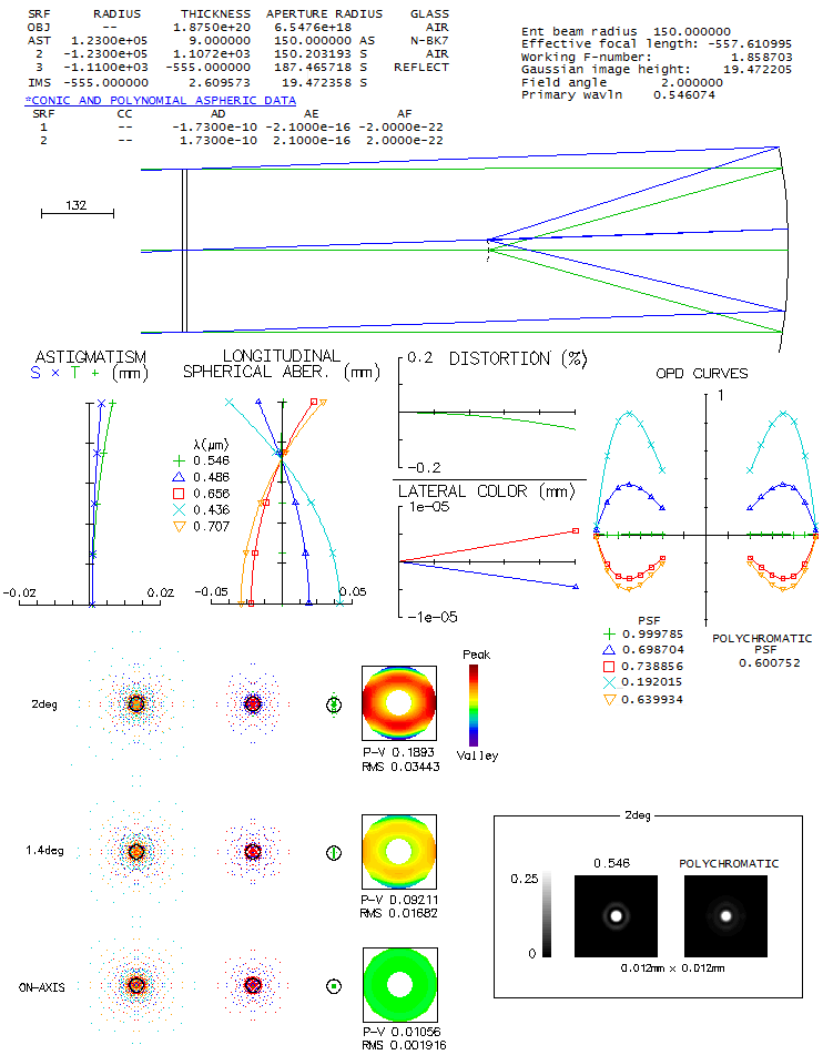
a drawing of a triplet catadioptric camera by Bernhard Schmidt caught my eye. It was
called an "alternative to the standard Schmidt", and made me curious:
just how close it is. Then, in an online PDF file which contained data
as close as possible to the prescription
(
Journal of Astronomical History and Heritage),
there was quite similar triplet camera patented by Houghton some 15-20
years latter (1944, US Pat.#2,350,112). Whether Houghton could know for Schmidt's work is
anyone's guess, but doesn't make less interesting finding out how do
these two cameras compare, and how close they come to the standard
(aspheric plate) Schmidt camera. For the Schmidt triplet, the original
handwritten prescription by Schmidt was used, scalled down to 100mm
aperture diameter, and optimized by very minor tweaks (there is also
a 1934. prototype of the same design which will be mentioned in
raytracing analysis). All three cameras are 100mm aperture f/1, to make them
directly comparable, and the field radius is 6 degrees.
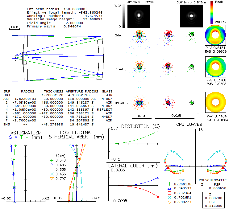
Image below shows raytrace of the downscaled Schmidt 3-lens catadioptric
camera. The the outer two lenses are plano-convex and symmetrical with
respect to the biconcave mid element. A single glass, probably Schott's
old O15 crown (nd=1.53, vd=58.99) was
used; since it is not listed in OSLO Edu catalogs, the closest found
was used (during rescaling the lenses got somewhat squeezed up; increasing
the gaps to 6.9mm, needed to clear axial pencil, doesn't
appreciably change the
output).
Central obstruction size is not given. Image size sets the minimum size
at 20% linear, which would practically have to be somewhat larger. Since
the effect is near-negligible, both central obstruction and (possible) spider vanes
are omitted.
LA graph shows relatively significant higher-order spherical residual
on axis. The corresponding wavefront errors for five selected wavelengths
are given by the OPD (optical path difference) plot. Best image surface
doesn't fall midway between the tangential and sagittal surface due to
the presence of odd secondary (Schwarzschild) aberrations (in presence of
spherical aberration, the astigmatism plot, originating at the paraxial
focus, is shifted away from best focus, but best image surface is vertical
when its radius coincides with the one entered in raytrace). While all
five wavelengths have a common focus for the 75% zone ray, their best
foci - mainly due to spherochromatism - do not coincide, resulting in
a nominally significant chromatism. Still, the g-line error is only
about three times the error in the optimized wavelength. The ray spot
plots indicate relatively insignificant chromatism (Airy disc is a
tiny black dot; its e-line diameter is 0.00133mm, or 1/300 of the
0.4mm line). Polychromatic diffraction blur exceeds 0.02mm at 4.1°
and 0.04mm at 6° off
(the five wavelengths, even sensitivity). Should be mentioned that
other than the prescription, there is an actual unit, a prototype
of this camera type from 1934. According to the measurements taken
by the paper authors, it is nearly identical to the prescription,
except that the middle element has slightly weaker radii (perhaps
fabrication inaccuracy). When scaled to the comparable 100mm f/1 system
(originally 125mm f/1.1) the overall correction is somewhat worse.
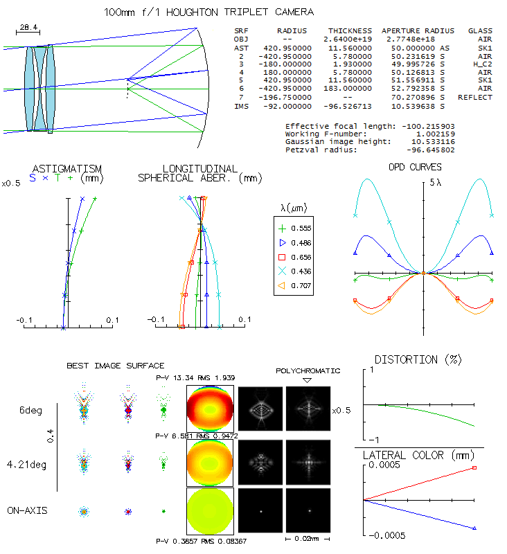
Houghton's patented camera differs in that it has two biconvex lenses
framing in the biconcave central element. Also, it uses two different
glasses. Again, there was no near-exact match listed for a glass quoted for
the mid element, but the one used for raytracing is close enough not
to make the end result significantly different (the minor optimizing
tweaks are probably in better part due to the small differences in
glass properties).
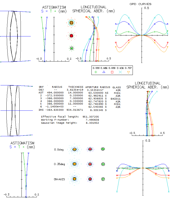
While the LA graph looks better on the first sight,
due to considerably lower higher-order spherical residual, chromatic
correction is significantly suboptimal due to the five wavelengths
having a common focus too high, at the 90% zone. It is larger by a
factor of 2.6 than what it would be if the common focus was at the
70.7% zone. The ray spot plots indicate more chromatism than in the
Schmidt configuration, but diffraction blurring is significantly reduced.
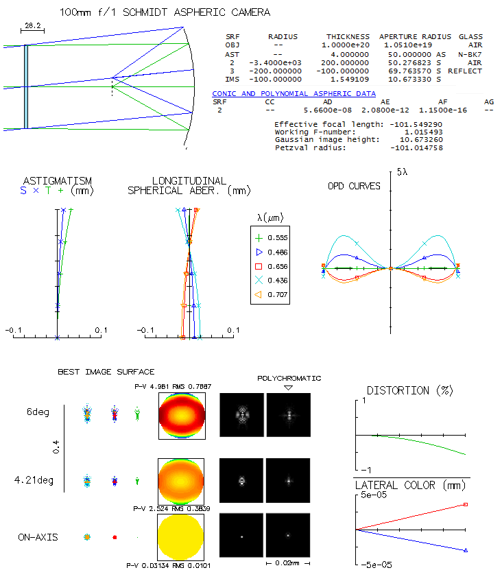
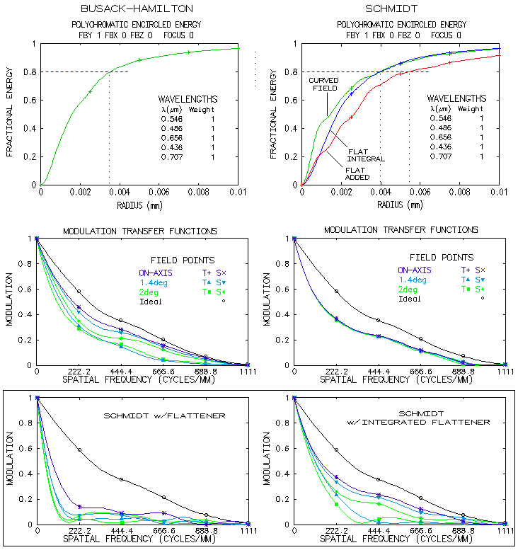
However, when compared to the standard Schmidt below, even the Houghton
falls significantly behind.
There is not so much difference in the astigmatism plot - which shows
primary and standard secondary astigmatism - but significantly smaller
ray spot plots
and diffraction images indicate much lower odd secondary aberrations.
Nominal chromatism (spherochromatism) is also significantly smaller,
but not so relative to the optimized wavelength, which is much better
corrected than with the 3-lens correctors. Overall superiority
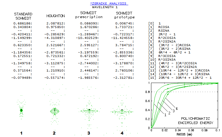
of aspheric plate is undisputable. It can be illustrated
with the magnitude of Zernike terms, and encircled energy, both 6°
off axis (below).
The standard Schmidt has only three significant terms, primary
astigmatism (#4), primary spherical (#8) and secondary astigmatism (#11).
The primary astigmatism term indicates 0.63 wave RMS (term divided by
√6), corresponding to
3.1 wave P-V, plus 0.43 wave RMS (2.7 wave P-V, term divided with √10) for secondary astigmatism.
That is more than ~4.5 waves P-V corresponding to ~0.02mm
longitudinal astigmatism on the plot, indicating the presence of
lateral astigmatism, of the same form as primary astigmatism, but
increasing with the 4th power of field angle, not included in the plot.
Similarly, the spherical aberration term indicates 0.53 wave RMS of primary
spherical aberration (term divided by √5), much more than what is present on axis. This is
due to the presence of lateral spherical aberration, of the same
form as the primary, but increasing with the square of field angle.
In the 3-lens Schmidt and Houghton, dominant term is primary astigmatism,
followed by primary spherical, secondary astigmatism, primary (#6) and
secondary coma (#13). Most of the terms are significantly higher than in the
standard Schmidt, and particularly for primary astigmatism. Simiarly
to the standard Schmidt, RMS error values indicated by the terms are
not in proportion to the graphical output, because it doesn't include
odd secondary Schwarzschild aberrations, lateral spherical, astigmatism
and coma. The ray spot plot in the paper is elongated vertically probably because
it is given for the plotted best astigmatic field not including odd secondary
aberrations; the actual best field, according to OSLO, is about 5% stronger
(also, spot structure is markedly different than for the one given by OSLO,
with the dense part of it for e-line more than twice larger than in OSLO:
over 0.05mm vs. 0.025mm; note that system in the paper has 25% larger
aperture, but also is somewhat slower, at f/1.13).
Polychromatic encircled energy plot (the 5 wavelengths, even
sensitivity) shows that the standard Schmidt has about three times
smaller 80% energy radius than its 3-lens corrector alternative, with the
Houghton midway between.
An interesting question is what aberration remain after taking out primary astigmatism. In the
standard Schmidt, it
originates at the corrector, usually is negligibly small, but at this extremely large relative
aperture and field angle it becomes significant. Since it originates at the corrector, it cannot
be minimized by changing corrector-to-mirror separation. The easiest way to do it is to midely
aspherize the mirror. With a small increase in mirror separation (3.9mm) and slightly different
best field curvature, practically astigmatism-free field is found - at least according to the
astigmatism plot. But then it becomes odd and conflicting. At 6° off axis, lateral spherical
is also gone, but the ray spot plot is somewhat larger, with nearly identical appearance as before.
Looking into the aberration coefficients, OSLO says there is no significant aberrations present,
with the largest terms being secondary and primary coma, while SYNOPSYS displays some low level of
coma, but also ellipticl coma (trefoil) and significantly larger oblique spherical aberration,
nearly twice as strong in tangential vs. sagittal plane (tagential and sagittal primary astigmatism are
very strong and practically equal, indicating zero primary astigmatism and very strong Petzval
curvature). Both, OSLO and SYNOPSYS give nearly identical astigmatism plot, with near-zero
astigmatism, as well as similar OPD plots - which are opposite in sign! Both OPD plots
show that wavefront deviation has the same sign in sagittal, as in tangential plane, but OSLO
wavefront map implies the sign is opposite.
Looking into OSLO Zernike analysis shows that the
wavefront deviation is mainly described with massive amounts of primary astigmatism and defocus,
with the only other appreciable terms (~10% of the error magnitude) being primary and secondary
spherical aberration. So, the nearly 10 waves P-V (12 waves in SYNOPSYS) of aberration mainly
aren't there in OSLO aberration coefficients, and are mainly attributed to "oblique spherical aberration"
in SYNOPSYS. The problem is that oblique spherical aberration should be rotationally symmetrical.
It is possible that what SYNOPSYS presents as lateral spherical aberration is secondary astigmatism
(which, like primary spherical aberration, changes with the 4th power of in-pupil height), and its
secondary astigmatism is lateral astigmatism, changing with the square of in-pupil height. If OSLO
does the same, but does not give the 4th power term, it would explain its actual aberration
being not supported with the coefficients.
In addition, the size of defocused ray spot plots indicates that the error is smaller focusing away from the
best astigmatic image surface (according to the astigmatism plot). That is not unusual in the presence of multiple
significant aberrations. The RMS wavefront error - and the ray spot plot - are nearly minimized
with ~0.025mm negative defocus (-96.8mm
image field curvature), rather significantly. Now, Zernike coefficients show as practically the only
form of the aberration primary astigmatism, which is also evident on the wavefront map. Hence, the
minimized RMS wavefront error focus at 6° off axis is nearly pure primary astigmatism, with no
trace of it either in OSLO, or SYNOPSYS aberration coefficients! As it is often the case with large
magnitude of aberrations, the RMS
wavefront error is not a reliable indicator of best focus; in this case, it is a mixed bag, with
the lowest RMS error focus having smaller 80% energy circle, but larger bright central core,
and having no advantage in the contrast transfer over the best astigmatic surface focus.
Flat-field quadruplets can come in various forms. The
particular arrangement given here is a contact air-spaced triplet
combined with a singlet meniscus at some distance behind
such as Ascar 130 PHQ from Sharpstar (its glasses are not
published, so that's where similarity ends). The triplet
does all corrections, central line and chromatic, but it is slightly
modified to compensate for the optical effect of the meniscus (it induces
corrective astigmatism and field curvature, but also significant amounts
of coma and spherical aberration). The
base triplet is NPN 130mm f/7.5 with Hoya's FCD1 and BCD11, given under
11.10 above. After adding the field-flattening meniscus, only
the 1st and last triplet radius were changed to correct for coma, and
one inner radius to correct for spherical aberration. However,
since the meniscus exerts negative power, the focal ratio went
from f/7.5 to f/8.6 (image below, top).
Field can be flattened with any meniscus form, but for minimized
lateral color a strongly curved meniscus is required. Off axis
monochromatic corretion is the best with the astigmatism cancelled,
and some slight residual field curvature remaining (flattening field
by indroducing a small amount of astigmatism roughly doubled the
edge field wavefront error). Meniscus location is
pretty flexible; cutting it in half only slightly worsens chromatic
correction. However, placing it right after the objective gives rise
to a significant higher-order spherical residual, due to correcting
for primary spherical requiring significantly larger inequality in
radius value between the three equal inner radii and the one correcting
for the spherical (trying to correct spherical by bending lenses
produces similar result).
One alternate way of correcting field curvature is by placing achromatized meniscus
significantly farther from the objective (bottom). The overall
chromatic correction is still good, but somewhat less than with
the above arrangement. The relative aperture also diminishes, to f/9.7.
The singlet meniscus extends the triplet's focal length by roughly 15%,
and the achromatized (more widely separaed) closer to 20%.
This means that these arrangements need to use triplets capable
of achieving good correction at f/6 to f/6.5 in order to produce
well corrected f/7 to f/7.5, or so, flat field systems.
Note that these are not necessarily the best glass
combinations, or separations: they illustrate general system
properties (however, with the singlet meniscus, as mentioned,
the differences are fairly small).
Does the triplet arrangement - NPN vs PNP - affects the outcame?
In general, like with the doublets, where reversing order of
positive and negative elements generaly has little effect on
chromatic correction, shouldn't be substantial, although it can be
significant in some respect. Ascar's 130 PHQ uses PNP triplet
which, since the positive element has to be ED glass, means it has
two ED glass elements. Similarly to the doublets, placing the
negative element in front requires significantly stronger inner
radii, because the glass used for it always have significantly
stronger index of refraction, requiring stronger radii to compensate
for the initial chromatic error by the weaker-index positive glass
(image below).
Significantly weaker inner radii of the PNP arrangement (bottom) seem
to be producing less spherochromatism and better overall correction. The exception
is the violet g-line, which is slightly worse, due to defocus, but the rest of lines
are significantly better. About twice smaller displacement of the
astigmatic field origin - which is by default at the paraxial focus -
indicates as much smaller spherical aberration in the e-line. However,
the NPN lens is set to produce the smallest error possible in the
g-line, which comes at a price of sub-optimal correction in the F and C.
By making the front radius 1-2mm stronger, F and C lines come to
their near-optimal correction, and the difference in F/C chromatic correction
becomes insignificant, while the g-line error becomes about 25% larger than in the
PNP. What remains unchanged is the twice larger
minimum error in the optimized wavelength.
ED doublets using lanthanum as mating element have become common these
days. While they leave something to be desired in the violet end
correction, their main advantage is their large Abbe# (dispersion)
differential vs. ED glasses, combined with sufficiently small relative
partial dispersion (RPD) differential to keep secondary spectrum
small to acceptable. Large Abbe# differential is a must for fast ED doublets, since the larger it is, the less
strongly curved inner radii required, and less higher-order spherical
aberration induced. Some other factors are also potentially significant -
like the refractive index ratio, actualy not favoring lanthanum in
general - but large enough Abbe# differential would compensate for
it too. The problem is that, due to the architecture of RPD diagram,
the larger Abbe# differential, the higher on it is lanthanum glass,
and the larger RPD differential vs. ED glass,
i.e. the larger becomes secondary spectrum (higher RPD is in general
offset by sufficently larger Abbe# differential, but the tendency is
secondary spectrum increase). Thus the choice of
lanthanum is always a compromise between a low higher-order spherical
residual, determining the central line correction level, and low secondary
spectrum. For the former the Abbe differential needs to be as high
as possible, for the latter - about as small as possible. The advantage
of high Abbe# ED glasses (~95) is that they can use lanthanums that are
lower on RPD diagram, i.e. with a smaller RPD differential, hence
smaller secondary spectrum as well. It will be illustrated how much
of a difference it makes vs. lower Abbe# ED glasses (~81), starting with
the latter.
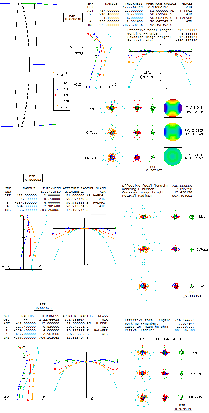
Raytrace below shows three variation of an ED doublet using Chinese
(CDGM) glasses, FK61 ED and lanthanum (these are similar to the
Astro-Tech 4" f/7 AT102ED). Doublet of this type has R2 significantly stronger
than R3. From the LA (longitudinal aberration) and OPD (optical path
difference, i.e. wavefront error) plots it is immediately visible
that the soft spot is correction in the violet. Top doublet uses
lanthanum with smaller Abbe# differential than the other two, hence
has higher secondary spherical residual, and higher minimum error in the
central line. The middle doublet has the highest Abbe# differential,
and the bottom one is in between the two. Photopic polychromatic Strehl
(0.43-0.67 micron, shown boxed) slightly favors the latter (note that
the Strehl values are for the location of best e-line focus; due to
the presence of secondary spectrum, best poly-Strehl is shifted toward
F/C lines - nearly 0.02mm for all three - 0.890, 0.898 and 0.903,
top to bottom, respectively). OSLO quotes
the price of its lanthanum glass as 5 times the BK7, vs. 3.5 times for the other two, which
makes the top combination most likely.
F and C lines are nearly balanced in the second and third combination,
at ~0.155 and ~0.125 wave RMS, respectively (0.53 and 0.44 wave P-v
of defocus), which puts them at the level of a 100mm f/24 and f/27 achromat, respectively.
The top combination has correction somewhat biased toward blue/violet,
with 0.074 wave RMS (0.26 wave P-V of defocus) in the F line, and 0.15
(0.52) in the C. If made nearly equal (g-line in that case goes over 1.1 wave P-V), they come at ~0.39 wave P-V
of defocus, comparable to f/31 100mm achromat. The middle combination
has significantly larger error in the violet, but it has little effect
on the photopic polychromatic Strehl, due to the low eye sensitivity to violet
in this mode. However, in the more appropriate to night-time observing,
mesopic mode, eye sensitivity to violet is significantly larger, and
this combination would have more effect on contrast (0.72 vs. 0.76
mesopic poly-Strehl vs. top combination, in part due to the higher sensitivity
in the red vs. green/yellow as well) in addition to more violet fringing.
This magnitude of violet defocus (comparable to that in a 100mm f/18
achromat) would be visible on bright objects, unless a special lanthanum
doped coating, selectively absorbing in violet, is applied (which was
likely the case with the APM 140mm f/7 lanthanum doublet).
Using ED glass with higher Abbe# - also called "super-dispersion"
(SD) - makes possible to use lanthanums
with higher Abbe#, with less of RPD differentiial, i.e. inducing less of secondary spectrum, assuming
the ED glass is of similar RPD value (FCD100/FPL53 have somewhat
lower RPD than FK61/FCD1, thus the advantage is partly offset).
Taking Hoya's FCD100 and two possible Hoya lanthanum matching glasses,
show reduced secondary spectrum, and significantly better correction
in the violet (these are similar to Astro-Tech 102EDL). As a result, the poly-Strehl is significantly higher
than with the lower Abbe# ED glass.
Due to the presence of secondary spectrum, best polychromatic
focus is shifted from the best optimized line focus (defocus Z in mm).
Despite its lower F/C error (0.07 vs. 0.08 wave RMS, when the two lines are
equilized), the top
combination has lower polychromatic Strehl, because its lower
optimized-line Strehl weighs more in the poly-Strehl value. But its
poly-to-optimized-line Strehl ratio shows that it has better
chromatic correction (0.962 vs. 0.954).
Interestingly, going somewhat slower while using the lower Abbe#
lanthanum glass in order to eliminate higher-order spherical residual
is likely to result in a small drop in the chromatic correction,
not only due to a bit more of secondary spectrum, but also
due to the higher-orderspherical actually reducing error in the blue/violet.
For example, taking 125mm f/7.8 AT125EDL configuration with assumed
matching lanthanum CDGM's H-LAF50B (equivalent of Ohara S-LAH66, or
Hoya's TAF1), with no higher-order spherical residual, produces
photopic poly-Strehl at the diffraction polychromatic focus of 0.923
(shown is objective with the positive element in front, but the
reverse arrangement produces identical correction).
Even at f/7 there is no higher-order spherical, and chromatic correction
is only slightly worse (0.912 poly-Strehl) but it was probably made
slower to be geared toward visual observers, since its violet
correction leaves something to be desired on CCD level. Visually,
its violet g-line (0.436μ) is at the level of a 100mm f/28 achromat
(or 60mm f/17), i.e. unintrusive. Its F/C correction is at the level
of a 100mm f/33 achromat.
Non-lanthanum alternatives at this fast f-ratios do exist for SD
glasses, but only a few. Short flints, like Schott N-KZFS2, paired
with FCD100, Ohara FPL55/53 or LZOS OK4 would
produce better overall correction, with the poly-Strehl exceeding 0.95.
Schott N-ZK7 crown would produce better chromatic correction than
lanthanums, but because of the central wavelength limit to 0.96+ due
to more of the higher-order spherical residual its poly-Strehl is
lower, at ~0.91 (the inner radii of such objective would be also very
strongly curved, requiring very tight fabrication and assembly tollerances). The best match for lanthanums is fluorite, which
has the highest RPD value, hence the high Abbe differential
lanthanums matched with it would produce less of secondary spectrum.
When comparing secondary spectrum
in ED doublets with that in achromats, it should be kept in mind that
even at near-identical error levels the effect is not the same,
because in the former the aberration is a more or less balanced mix of
6th and 4th order spherical, with some amount of defocus, while in the
latter it is mainly defocus. They have different forms of intensity
distribution, and in so much different effect on contrast. Good indication
of this difference is given by their respective MTF plots (below).
Since at these (low to moderate) error levels spherical aberration
spreads energy wider (it is not fully apparent at the intensity
normalized to 0.1 shown, but would be more visible at lower normalization
values, or with logarithmic base), it causes more
of a contrast loss at low frequencies, but less at mid frequencies,
where is the approximate cutoff for bright low-contrast objects,
like planetary surfaces.
However, it is again more detrimental at high frequencies (lunar,
doubles, globulars). Diffraction simulations for 6th/4th order spherical
are based on the actual F-line wavefronts in the ED doublets, and defocus simulations are
pure defocus.
It was demonstated above that optical plastics can work well
replacing glass in an achromat. How well they can work as a
matching element to ED glass? Here's what it looks like with
some of plastic materials listed in OSLO Edu. Objective is 80mm
f/7, alike AT80ED, which is not using lanthanum (and probably
couldn't considering its low price), and cheap suitable crowns
have too small Abbe# differential to work well at f/7. It is not
to imply AT80ED uses plastic mating element, but it is a possibility.
With what appears to be a mix of styrene and acrylic (top), correction
in F and C is very good, just over 0.2 wave P-V of defocus. It is
comparable to a 100mm f/56 achromat, and satisfies the "tru apo"
requirement. At about 1 wave P-V, the red r line is at the
level of a 100mm f/22 achromat, while 4.1 wave P-V in the violet
g line puts it at the level of a 100mm f/14.5 achromat.
Using carbonate as mating element (bottom) produces markedly better
correction in the violet, but worse in the other three lines. With
just over 0.8 wave P-V in F and C, it is comparable to a 100mm f/15
achromat, with the red r line at the level of f/12, and
violet g line f/15. Other plastics did not produce good
correction levels, but it is very likely that better correction
than these two shown are possible. Of course, using plastics for triplets
widens the possibilities. These two combined, with STYAC in front
(reversed order is not as good) produce f/7 system with F/C lines
at the level of a 100mm f/12 achromat, and the violet g-line more than
2.5 times better, i.e. at the f/31 level. Still better is FK61/CARBO/STYAC
f/7 arrangement, with F/C at the level of a 100mm f/15 achromat, and
g-line at the level of f/25. These are unusual modes of
correction, illustrating that use of plastics could enhance both
correction level and correction choices in lens objectives
(note that optically there is no difference between the standard H-FK61 glass
and low-softening-temperature, moldable D-FK61, but the latter is nearly twice
more expensive).
Plastics have the advantage of being lighter, but their other physical
and chemical properties so should be at least close to those of
optical glass. As the production technology advances, it will be
becoming more viable as a glass substitute.
Different brands of this eyepiece come with anywhere from 44°
(Celestron) to 52° (Orion, Meade "Super Plossl", generic brands)
apparent fieldof view (AFOV) claimed. Taking that the apsolute
limit for the field stop
radius is the inner radius of the 1.25" barrel - around 14mm -
implying 23.6° zero-distortion angular field (~47° diameter),
the limit to the AFOV is imposed by field distortion. In most cases,
distortion is positive, enlarging image away from axis, in which
case the AFOV is bigger than zero-distortion FOV according to the
extent of distortion. For Plossl eyepiece, it is about 10%,
implying nearly 52°. Raytrace exercise below tells somewhat
different story (it is illustrated using Plossl design, but in
general can be applied to any other).
Top design is downscaled Plossl from the Rutten/Venrooij's book.
Reverse raytracing shows that the size of optical image is 14.2mm,
a bit over 14mm, implying 25.6° (51.2° diameter) as the
limit to AFOV. Design below, the upscaled patented Nagler Plossl
design, implies 26.5° (53° diameter) limit. The difference comes from different
distortion rates: the Nagler has somewhat larger distortion,
resulting in a larger AFOV transmitted (note that reverse
raytracing gives distortion of opposite sign to the actual
distortion, hence zero-distortion - or Gaussian - image is larger
than the optical image, showing so called barrel distortion).
However, the numbers come out differently with direct raytracing
- at least at first sight. The Nagler Plossl is plugged in with
two "perfect lenses": one for the 125mm f/8 objective, and
the other one at the eye end with a 17mm f.l.
Here, the true field angle just fitting into 14mm barrel radius
is 0.80°. With the objective focal length of 1000mm, and the
corresponding 31.25x magnification, the zero-distortion field
radius is 25°. That is 2.4° more than what the field stop
radius vs. eyepiece f.l. implies. The larger field produces
higher distortion (in proportion to the 3rd power of field radius),
now about 14%, with the coresponding 57° AFOV. Anyway, that
would be the usual way of calculating it. However, magnification
is not defined as magnification of the angle, rather as
magnification of its tangent. So the correct AFOV in this case
can be found from: (1) multiplying tan(0.8°) with 32mm f.l. to obtain
unmagnified height corresponding to the eyepiece focal length,
(2) having that height multiplied with 31.25x
magnification, and (3) from arctan of that height divided by 32mm
f.l. obtain the corresponding zero-distortion angle of view.
In this case, the unmagnified height is 0.447mm, the magnified
one is 13.96mm, and the corresponding zero-distortion angle is
23.6° (47.2° in diameter). With 14% positive (pincushion)
distortion, it gives 53.8° AFOV. It is less than a degree larger
than the AFOV obtained directly from the stop radius vs. eyepiece
f.l., i.e. the corresponding angle, multiplied with the distortion
ratio. This difference is most likely due to rounding off the nominal
distortion numbers.
The size of
transmitted AFOV doesn't depend on barrel length, or stop (i.e.
image) location within it - the last passing cone is vignetted
by over 50%, and the very next one higher is not making it trough at all.
Its change with the focal ratio (f/8 shown) is negligible.
There is little use of an oversized field lens transmission-wise, but
it is desirable in order to avoid light passing near the very edge
of a lens. Placing a 1mm wide stop into the barrel would reduce
the opening to 12mm radius, with the corresponding zero-distortion
field radius reduced to 20.25°, and the corresponding
AFOV to 22° (44° AFOV diameter). So, the answer is: it
is possible to pack 52° AFOV into 32mm 1.25" barrel eyepiece,
but only with no field stop in the barrel.
What happens when the apparent field of a standard eyepiece, such as Plossl,
extends well beyond its usual 50 degrees? If, for instance, the same
Nagler Plossl from above is to expand to 80° AFOV? Image below
shows reverse raytrace of this design with the angle of divergence
from the aperture stop - in effect the exit pupil of the eyepiece -
equal to 40° (top). Obviously, the field lens had to be enlarged
in order to accept the wider field, but the astigmatic field looks
relatively good, with the astigmatism magnitude remaining nearly unchanged
over the last 30% of field radius. There is some field curvature, but
quite acceptable: edge of field best focus is less than 2mm away from
the field center focus. For 32mm f.l. eyepiece - from 322/1000 -
it translates to less than +2 diopters of accommodation
(infinity to over 0.5m distance). Distortion of about -30% means that
in the actual use the zero-distortion field - the
one determined by the eyepiece field stop - would be 56-57°.
However, coma - which increases
with the 3rd power of aperture (i.e. cone width) vs. astigmatism
increasing with the 2nd power - becomes obvious in
the outer field. Also, lateral chromatism is unacceptably large in
the mid 50%, or so, of the field radius. Coma can be diminished by
flattening R6 while strengthening R1 which, with the change of glasses, also lowers
astigmatism over most of the field, as well as lateral color error
(bottom). But longitudinal chromatism is significantly larger, and
field curvature is significntly more demanding: field edge requires
nearly +4.5 accommodation (infinity to ~0.24m distance).
Taking a compromise with some more astigmatism but flatter field
gives what is shown below (top). Note that
in reverse raytracing Gaussian image height is that of the apparent image (dashed line)
and the actual, zero-distortion image, determined by the converging marginal cone,
is the actual, "aberrated" image. Similarly, diverging cones entering
field lens are unequal in width - a consequence of the all field
pencils passing through aperture stop (i.e. eyepiece eit pupil) being
by default of equal width. The wider marginal converging cone
indicates lower magnification (by forming smaller Airy disc, i.e.
image scale), resulting in the negative (barrel) distortion.
Note that the half-diagonal of the square representing zero-distortion
(Gaussian) image equals the Gaussian image height (radius) in the image plane.
But
to find out how it is actually working in a telescope, it is
necessary to raytrace directly (bottom). The eyepiece is now working with the
field produced by a 100/1000mm (f/10) "perfect lens", and another
perfect lens is used on the opposite end to form the image. Field angle
needed for identical edge point height in front of the field lens is
1.09°, or 19.08mm. The
resulting astigmatic field is now significantly changed, with strong
higher-order astigmatism dominating the peripheral field. It is a
consequence of different ray geometry, with the diverging cones
coming from the objective being of the same width at the field lens,
while the marginal cone pencil exiting the eyepiece is, for that reason,
significantly more narrow than the axial pencil
(this is causing it reaching the retina as a narrower converging
cone, forming larger Airy disc i.e. generating positive image distortion).
Different ray geometry also results in uncorrected lateral chromatism
as well. Higher order astigmatism is lowered by weakening R4 which,
with corresponding change in the glasses, produces a better performing
design, as it would look like in the actual use (bottom; weakening R4
increased the focal length to 33.4mm, and to compensate for that the
field angle is increased to 1.14°). This
particular modality has astigmatism minimized at the field edge,
but with minor changes in the radius it can be increased at the edge
while decreased in the inner field. With the nominal distortion of
+40%, the actual (zero-distortion) field is 57°. The eyepiece
would be usable at mid to slow focal ratios, but it would have
nearly double distortion of more complex designs with Smyth lens
(even Erfle-type eyepieces have generally lower distortion over
wider a field than the standard Plossl's).
It is not uncommon with Newtonian reflectors that bottom end
of the focuser protrudes into incoming light. Here, the effect
is given for a 50mm wide focuser tube protruding 25mm into the
axial pencil of light falling onto a 200m diameter mirror.
By area, it is just below 4%, comparable
in that respect to 0.20D (20%) linear central obstruction.
While the central obstruction effect is considered generally
negligible, the effect of protruding focuser may not be.
Obstruction by focuser tube makes central diffraction maxima
elongated in the direction of focuser. The PSF shows that
the perpendicular maxima radius is slightly smaller than that
of a perfect aperture, but te elongated radius is about 10%
longer. The consequence is a contrast drop incerasing with
orientation change, maxing out for the orientation along
the elongated radius, where the effect is similar to that of
5% reduction in aperture diameter. Obviously, the same area of
protrusion will cause less of obscuration, and less of an
effect with a larger mirror, and more with the smaller one.
Mirror clips are pretty common in Newtonian reflectors, and
can be found in other instruments using mirrors to collect light.
The relative mirror area they are obscuring is generally small,
but speculations run wild about their diffraction effect,
particularly spikes that they might be causing. This simulation
by OSLO Edu shows no spikes to worry about as far as
mirror clips are concerned - and little else to worry about altogether.
A 200mm diameter mirror with three 12x6mm clips (as the area over
the mirror surface) which block less than 0.7% of incoming light, and
the effect is commensurate. The only visible change in the PSF,
barely noticeable at intensity normalized to 0.01 (top, middle)
are sections of uneven intensity in the 3rd bright ring. Normalizing
down to 0.001 brings down similar structure in the subsequent
bright rings, but the MTF shows that the overall effect is
negligible. Enlarging clips area to 1.5% (bottom, comparable in
area to 0.125D linear central obstruction) still shows no
sign of spikes in the bright pattern area (note that it is now doubled,
0.1mm square side vs. 0.05mm above). Normalizing intensity down to 0.001 -
which means that all points brighter than 0.1% of the central intensity
are white - brings out faint outer areas where there is a
hexagonal (primary) spike structure developing, but the intensity
of these spikes is too low for them to become visible in
general observing. The MTF is still not showing appreciable
contrast loss, so the conclusion is that mirror clips do not
produce neither visible diffraction artifacts, nor noticeable
loss of contrast.
As an illustration of difference in chromatic correction between
objective using ordinary glasses and those using special glasses,
an ordinary (BK7/F3) 200mm f/15 achromat is compared to two designs
by Klaas Companar: one using Schott FK51 extra-dispersion glass with
KZFSN2 short flint, and the other using fluorite with Schott Lak9
lanthanum glass (p56-59). They are both significantly faster,
with the ED doublet at f/10, and the fluorite doublet at f/8;
the former has 4.6 times lower secondary spectrum, and the
latter only half as much of it, or over 9 times lower than the
achromat. The ray spot plots given suggest that the two objectives
with special glasses are much better corrected. If the difference
in focal ratios, i.e. Airy disc size is taken into account, the
advantage of special glasses is significantly lessened, but still
substantial. However, do the spot sizes tell all the story?
If we look at the polychromatic Strehl, the difference becomes
unimpressive. At the best diffraction focus, the achromat scores
0.747, ED doublet 0.826 and fluorite 0.813 (430-670nm, photopic
sensitivity). Because of its poor correction in the violet, the achromat
falls farther behind for mesopic sensitivity (closer to night-time
observing): 0.547 vs. 0.763 and 0.757, respectively. Converted to the
corresponding P-V wavefront error of primary spherical aberration,
it relates as a bit more than 0.4 vs. a bit less than 0.3 waves.
And taken to the standard, photopic sensitivity, it becomes even
less impressive (for the special glass) 0.28 vs. 0.23-0.24, in the same
order. We should state that blur size comparison is strictly valid
only for a single type of aberration (here we have defocus with the
achromat and spherical+defocus with the other two), but the main reason
for disappointing performance of the special glasses is suboptimal
design. Raytrace below shows the two objectives as given in the book
(top two) and near their optimum (bottom two; prescriptions are for
the optimized objectives). Note that OPD (optical path difference,
or wavefront deviation) scale - given in units of wavelength on
vertical axis - is different for the two objectives, because of the
larger violet error of the fluorite objective.
For some reason, designer wanted to bring together marginal foci
of the blue F and red C line. Not only that the error at this focus
location is four times the error at the 0.71 zone, this common focus
is farther from the green focus, which makes the error in F and C even
larger. The only benefit is better correction in the violet, but if
it comes at a price of worsening correction in all other non-optimized
wavelengths, it has to result in inferior performance. Bringing the F and C
0.71 zones together (bottom two), minimizes error not only in those
two wavelengths, but also in most of the others. The result is
photopic Strehl of 0.955 for Apoklaas and 0.927 for fluorite (value
under Z is defocus needed from the e-line focus to the best diffraction
focus). Note that the Strehl is in a smaller part better because of the
minimized error in the optimized wavelength as well.
Not long ago, refractors using ED glasses for secondary spectrum
correction were very expensive. One solution to the problem was
offered by Valery Deryuzhin, in the form of subaperture corrector,
which he named Chromacor.
Its prescription was never published, but Roger Ceragioli tried to
find out what can be done with such corrector, and results are
pretty good, at least over limited field (note that Deryuzhin stated it still falls behind his
Chromacor correction wise, especially with respect to lateral
color error).
Top raytrace shows the 6" f/7.9 achromat alone (it was probably
intended to be 150mm f/8, but the difference is negligible).
Bottom raytrace shows correction level with the corrector
added (like Chromacor, it consists of 5 cemented lenses). Correction
is at the "true apo" level in the violet g-line (0.85 Strehl), but falling short
of it in the F-line (0.66 Strehl) and, more so, in the red. But even the red end
is several times better
corrected than in the achromat. More specifically, the red C-line,
as indicated by the OPD graph, is less than 1/2 wave P-V, or at the
level of a 100mm f/27 achromat (with nearly balanced C and F lines).
F-line, at 1/3 wave P-V is at the level of a 100mm f/36 achromat.
Central line correction is even better with then without corrector
(note that the ray spot plot size is not in agreement with other
values, and should be more than twice larger - probably some kind of
a glitch; the other spot sizes, including the central line's for the
achromat alone, appear to be in line with the P-V
wavefront error values).
Diffraction images bottom left show lateral
color error, limiting quality field radius to about 0.05°,
when the blue Airy disc starts visibly separating from the green-yellow
Airy disc; at that point the polychromatic Strehl (photopic) is
around 0.80 - in the absence of any other aberration
(note that diffraction images are enlarged vs. ray spot plots,
roughly by a factor of 2;
also, color code for them is different than for ray spot plots).
In general, the benefits of a faster system are wider fields achievable
and gain in "speed" (CCD/photography). Dedicated reducers can also
flatten image field, and/or correct aberrations inherent to the system.
Here, it will be examined how well can a common cemented objective
corrected for infinity function as a focal reducer. Let's start with a
100mm f/12 achromat. As image below shows, the maximum visual field that fits
in a 2" barrel is a bit over 2 degrees in diameter. Placing a 600mm f.l.
cemented doublet about 300mm in front of its focal plane turns it
into an f/8 system.
Now, the entire 2-degree field can fit in a 1.25" barrel, or if 2"
barrel eyepieces are used, it can expand up to 3.2°. The effect
on chromatic correction is nearly negligible, as OPD graphs show,
but the reducer adds nearly 1/11 wave of undercorrection. Best field
curvature, however, is significantly more relaxed - 1800mm vs. 430mm - with the
reducer lens (ray spot plots are for the best field, for e, F and C
lines only). The reducer is fairly insensitive with respect to its
placement point: as much as several mm deviations will weakly affect the reduction ratio, with
no appreciable effect on the correction level. This particular cemented objective uses Schott SF5 flint,
because it allows for near-optimal correction with BK7, but any
well made cemented objective should have similar effect: reduced
focal ratio with the chromatic correction level of the original system.
In this case, a 100mm f/8 achromat with chromatism of an f/12 system.
With Cassegrain-like systems, there is no gain in field size from
using reducer lens, since it is limited by the baffle tube rear
opening and in most cases can be fully accepted by 2-inch barrel.
Only large systems, with baffle tube opening wider
than 2" could gain significant extra field from the use of a
reducer lens. Otherwise, the gain limits to possibly be able to
pack the useable field into 1.25" barrel.
Just recently, someone on a Russian forum wanted to know if he
could expand usable field of his Santel Maksutov-Cassegrain with
a reducer lens, so that he could fit the entire Pleyades into the view.
Below is an exercise with what should be close to the Santel MK91,
a 230mm f/13.5 system. Placing the same type of cemented doublet
objective inside its baffle tube reduces (expands is more
appropriate word) its focal ratio to f/9, packing up the original
near maximal 0.8° field into 1.25" barrel. The original field
with ~40% edge illumination - the minimum acceptable visually -
is 1.1°, assuming 46mm rear baffle tube opening, same as
Celestron 9.25. With the reducer, field diameter with nearly
identical edge illumination is 1.2°, for the nearly 10% gain.
Main effects of the reducer lens are somewhat worsened g-line
correction (still safely within the "true apo" requirement), and
2.5 stronger astigmatism for given angular field (2.5 times 2.25
for given linear field). Stronger astigmatism, however, makes
best image surface significantly more relaxed: 2000mm vs. 500mm
w/o reducer lens. Diffraction image of a star at 0.6° off
axis is approx. 0.05mm, which for a 50mm eyepiece, needed for
near 6mm eit pupil, translates into 3.4 arc minutes - borderline
between appearing as a point source and not to the average eye
(from 0.05x57.3x60/50).
With the Nagler 31mm and a comparable linear field size, it would
increase to 5.5 arc minutes - soft, but acceptable for field edge.
System above assumes moving focusing tube, capable of handling
the shorter back focal length due to the presence of a reducer lens.
More often than not, Maksutov-Cassegrain systems come with mirror
focusing instead. In that case, by reducing mirror separation
back focal length is extended to the eyepiece field stop, with
the eyepiece shoulder remaining at a given, permanent location.
The efect of extention is illustrated on a
5" f/12
Maksutov-Cassegrain telescope with aspherised primary
(the one at right, with a regular D/10 meniscus thickness).
Raytrace below shows that the back focus extension has relatively small
effect (before extension -top, after - bottom).
In the prescription, boxed numbers show changed values (that matter)
due to the extention. It caused focal ratio to change from f/9.5 to
f/8.7, adding some more astigmatism which made the best field curvature
yet less strongly curved. Longitudinal astigmatism is over 0.8mm vs.
less than 0.5mm in the original arrangement, but since the wavefront
error changes in inverse proportion to the focal ratio number, astigmatism is
over three times larger. Still, the 0.7° diffraction spot size of roughly
0.06mm implies off axis performance nearly as good as with the
Santel above (w/reducer). Field illumination and angular size remain very
similar to those without reducer lens, only the field is scaled
down linearly and fits into 1.25" barrel. There would be little
use of trying to expand this field with 2" eyepieces, since
field illumination rapidly drops below acceptable.
The very first actual instrument built according to Maksutov's
prescription during the WW2 was a small 100mm aperture Maksutov-Gregorian,
intended for educational purposes in elementary schools and for
public at large. The original prescription exists in Maksutov
papers, and it raytraces as shown below. It's LA graph is leaning
to the left, indicating suboptimal correction, and the shear
magnitude of aberration is already unaceptably large. Color
correction is also suboptimal, since the blue and violet (more so)
need to have their inner zones focusing longer, and their
outer zones focusing shorter than those of the longer
wavelengths. As if it isn't bad enough, the image forms just
in front of the primary's
surface, which severely limits its accessibility. Is it possible
that Maksutov was so sloppy with the first embodiment of his new
telescope?
As for the image location, the telescope was supposed to be very
simple (read: cheap as possible), so the stick-in eyepiece was a
part of achieving that goal. Only longer focal length eyepieces
were usable, limiting the highest magnification to about 40x.
That was probably why it didn't matter that the central line error
was nearly 0.4 waves P-V, or 0.13 wave RMS (balanced 6th/4th order
spherical, within annulus with 40% linear central obstruction,
comparable to 0.44 waves of primary spherical w/o central obstruction).
Note that raytrace measures the P-V error from the non-existing
center, hence its figure is significantly larger than the actual
P-V error of the wavefront within the annulus.
Also, taking a closer look at the central line error reveals that
the correction level determined by Maksutov's prescription is the
one with the highest Strehl, and with only slightly larger 80% energy
radius than the best possible. Main reason for this is that the central
obstruction is large enough to cause the Strehl to peak not at the
focus location with the lowest RMS error in the absence of obstruction -
i.e. when a line connecting
paraxial and edge zone focus on the LA graph
is nearly vertical - but at a slightly different
focus location, for which the wavefront deviation within the annulus
is minimal. The lowest nominal P-V wavefront error is, as the
OPD graph shows, an artifact of the measurement being done from the
origin, where no actual wavefront is present due to obscuration
by central obstruction. The actual wavefront error in the annulus is
significantly larger for this focus point than for any of the three
others.
Some time later, higher-order aspheric was applied to the primary
in order to reduce the excessive spherical aberration of the original
instrument. Reportedly, it allowed use of 200x magnification (presumably,
image was made accessible to shorter focal length eyepieces). No
specifics of the aspheric applied were given, but if we assume
that it was a complete correction (even the 8th order term is not
negligible), resulting rytrace is shown at the bottom, left. The sub-optimal
color correction becomes more obvious, and it cannot be improved
without changing corrector lens itself. For given meniscus thickness,
the radii would need to be somewhat shorter (small box bottom right),
but it would leave the image hopelessly inaccessible. By making
meniscus nearly 2mm thicker, the color error can be minimized with
the image a few mm closer. The reduction is much greater than what
the respective ray spot plots indicate, because the defocus error is
replaced by spherical aberration error; for given error magnitude,
defocus spot is 4.5 times smaller than that for primary spherical
aberration, and more so for the higher-orders.
Wavefront error is 6-7 times smaller in the red and blue, and
about four times in the violet. That said, the original correction
was at the level of a 100mm f/25 achromat, with that error nearly
cut in half by putting higher-order aspheric on the primary. That
would take it close to the "true apo" minimum. Considering that,
it is more likely
that the sub-optimal color correction was also a result of cutting corners
than design error, i.e. settling with somewhat thinner meniscus than
what is needed for the best correction.
It is known that Petzval arrangement makes possible to flatten image
field, and to achieve high level of correction, both monochromatic
and chromatic aberrations. While the flat field advantage is
undisputed, how does it compare to a triplet objective correction-wise? To try to
answer that, will raytrace two 140mm f/7 apochromatic arrangements.
To make them fully comparable, they both use the same two glasses.
As shown below, the triplet comfortably passes the "true apo"
criterions, with the polychromatic Strehl (430-670nm, photopic)
a bit short of 0.97. Note that this combination can't be made
into objective with two pairs of identical radii (suitable for oiling) without
aspherizing; since that wouldn't appreciably effect correction
level - and to keep the two fully comparable - it is left all
spherical, same as the Petzval. Looking below, we see that the
Petzval arrangement has better correction in the central line, as
well as tighter colors, resulting in the 0.98+ Strehl. Also, field
astigmatism is more than twice lower: while at 1° off axis
the triplet has diffraction pattern expanded into 0.015mm astigmatic
blur, in the Petzval the central maxima remains nearly intact.
Petzval's advantage becomes more obvious with faster focal ratios.
If, for instance, we go down to f/5.3, its central line correction
is practically unchanged (one advantage of the Petzval is that it
allows for the higher order residual to be practically eliminated
w/o aspherizing). There is more chromatism, but even at this fast
focal ratio and at that aperture it is flirting with the "true apo".
And the triplet - which can simply be scaled down with minor tweaks,
as opposed to the Petzval which needs some more substantial changes
(radii 327.6/172.2/172.2/926.8/-172.2/-174.02/-694.4, axial thickness
9/2.3/14.8/546/14/0.7/7) -
is now behind in the central line correction, and even more in its
chromatic correction. Summing it up with the poly-Strehl, it comes to
0.87 vs. 0.93 for the Petzval. Linear astigmatism didn't change,
but since the wavefront error is inversely proportional to the square of focal ratio,
it is about 75% larger in both. With the triplet, it means as much
larger astigmatic blur (~0.026mm), and in the Petzval it just reaches
the level when the diffraction image at 1° off starts turning into a small cross.
If downscaled to 100mm aperture, the Petzval comfortably passes
the "true apo" test.
In his book "Astronomical Optics", Maksutov gives prescription
for 1m f/9.8 Maksutov-Cassegrain that would be both better corrected
and (much) more compact than refractors of that aperture size -
its tube would be less than 2m long (2nd ed. 1979, p352).
However, with an f/2 primary such a large meniscus would
generate very large higher-order spherical aberration
residual, which would, even after minimizing it by balancing with
the lower order, render it unusable. Hence, Maksutov writes,
either the front meniscus surface, or primary mirror, have to be
aspherized in order to have spherical aberration corrected. He
states that a slightly deeper than 1 micron aspheric on the
primary would do the job, but there is no specific data for
aspherization. Just how good such telescope would be?
Shown below is the system as given in the book, all spherical
(top), with aspheric on the primary to do away with spherical
aberration (middle), and with aspheric on the primary needed
to correct spherical aberration and minimize coma (bottom).
Central obstruction is taken to be 30% by diameter, which is
about the practical minimum for this configuration.
As raytrace shows, the all-spherical arrangement is hopelessly
crippled by spherical aberration. Removing it requires use of
three successive aspheric terms: 4th, 6th and 8th order, for
primary, secondary and tertiary spherical aberration (taking
out the 8th term would leave in as much as 2.5 waves P-V of
tertiary spherical, which could be minimized by balancing it
with secondary spherical, but would still remain roughly at
the 1/2 wave P-V level). The first term is same as conic,
with the corresponding value given from K=8(d4)A4,
where d is the aperture semidiameter and A4 the 4th order
coefficient (in this case, K=-0.119, with the minus sign
coming from the positive A4 value for mirror surface oriented
to left, i.e. with the negative sagitta value). The significance
of this term (i.e. conic) is that it induces primary coma: in this case,
positive coma offsetting the native negative primary coma of the
all-spherical arrangement. However, this conic value offsets less than
half of the original coma, leaving the field quality with
much to be desired. For fully minimizing coma, more than
twice stronger conic is needed, with the excess, or rather,
lack of primary
spherical aberration compensated for by changing corrector radii
(making them more relaxed).
But, according to the book,
what Maksutov had in mind is correcting for spherical aberration
alone. That would put visual "diffraction-limited" (0.80
Strehl) field radius at 2.9mm, or 0.017°, with the diffraction
blur at 0.25° off roughly 0.12mm (nerly 2 arc seconds) in
diameter. The value of higher-order terms, given by Aidi,
where i is the order, and d the aperture semidiameter,
gives the needed
edge depth of the aspheric as δ=0.014875-0.006625-0.0008984=0.007352mm,
or 7.35 microns. That is much more than 1 micron stated by Maksutov,
which indicates that he had in mind aspherization for the best
focus location, not the paraxial focus, as OSLO is set to do. Knowing
that the best focus error is four times smaller for
primary, about 2.5 times for secondary, and nearly two times for
tertiary spherical,
the needed maximum depth comes to 0.62 microns, approximately at the
0.72 zone. Neglecting tertiary spherical, the depth is 1.07 microns,
nearly identical to Maksutov's figure. Apparently, Maksutov went
with the first two terms only, and if the third term is included the needed
depth is almost cut in half. Since the maximum depth is at the ~0.72
zone, not at the edge as with the paraxial focus terms, the
corresponding volume of glass to remove is significantly smaller than what the
depth figures alone indicate.
Since including the third term not only improves axial correction,
but also makes the aspheric shallower, it is the best option. It
is therefore shown for both, system corrected for spherical
aberration only (middle), and the one corrected for spherical
aberration and coma (bottom). A4 term implies that the conic needed for minimizing
coma, by balancing its lower order form, affected by mirror conic,
with its nearly constant higher order form, is K=-0.23425. The gain
in field correction is significant: "diffraction-limited" field
radius increases to 0.105° (17.8mm), and the diffraction blur
at 0.25° is about 2.5 times smaller, with the 80% encircled
energy radius smaller as much as four times (0.02 vs. 0.08mm,
or 0.42 vs. 1.68 arc seconds). Spherochromatism is significntly
reduced in the last arrangement (0.905 poly-Strehl vs. 0.838), due to its more relaxed meniscus
radii. Astigmatism as also reduced, by some 20%, to ~0.85 wave P-V.
The price to pay for these
is significantly deeper aspheric - 5.3 microns - due to the larger
A4 (i.e. conic) and smaller A6 and A8 terms (higher-order aberrations are
reduced because of more relaxed corrector radii).
If the back focal length is kept
nearly unchanged, the system becomes somewhat faster, at f/9.3.
Bottomm left illustrates needed modification of the sphere by
the paraxial focus (OSLO) aspheric terms. The A6 and A8 terms
are exaggerated vs. A4 - although in the previous arrangement
A6 was about half as large as A4 - and the latter is exaggerated vs.
starting sphere, for clarity. As mentioned, aspheric based on
the best focus correction would have its maximum depth at about
0.72 zone, with no glass to remove at the center and the edge;
depth of such aspheric would have been a small fraction of the
depth shown in this illustration.
The system proposed by Maksutov has two big advantages vs.
similar aperture refractor: color correction, and compactness.
For comparison, the
Yerkes 1-m refractor is 19m long, with its
F/C blur measuring nearly 0.7mm (7.5 arc seconds) in diameter.
The aspheric required for the Maksutov is not excessive
for the last arrangement, and is quite low for the
middle one,
so it can be regarded as a better overall alternative. Even with
the coma left in, the 1m Maksutov at 0.25° has 80% EE radius
0.0799mm, vs. 0.0749mm on axis for the Yerkes refractor (photopic
sensitivity), hence having better correction for the smaller fields.
My first telescope was made of a pair of identical spectacle lenses -
the pre-cut, round shape, placed at half the focal length separation
which - as a source I was using stated - was minimizing chromatism (in
fact, chromatism is larger than that of the single lens, but it is
lower than chromatism of a single lens with focal length equaling
that of the two lenses combined).
Those were probably +1 diopter (1m f.l.), round lenses, about 50mm in
diameter, stopped down to 25mm, or so, clear opening with a
diaphragm. I did see more with, than without it, although it was
certainly more colorful too. These are simple to make and inexpensive
telescopes, but how good they really are? To find out, will raytrace
such a system.
Nowadays, spectacle lenses are made of synthetic materials, such as
CR39 plastic, acrylic or polycarbonate. CR39 and acrylic have properties
similar to the common crown glass, while polycarbonate has significantly
different dispersion and generally produces more chromatism. Image
below shows raytracing results for a +1D acrylic lens stopped down
to 25mm. That produces a 25mm f/41 singlet lens telescope objective.
Longitudinal chromatism, as expected, is in the form of
primary chromatism, i.e. with shorter wavelenghts focusing shorter,
and longer wavelength longer than the optimized, central wavelength.
With these particular parameters, defocus wavefront error is 1.25 wave
P-V in the blue F-line, and 1.06 wave in the red C-line. Average for the
two, 1.15 waves, nominally corresponds to a 100mm f/10.4 achromat,
but the actual chromatism for any given F/C error level is significantly
greater with primary spectrum. That is because the defocus error
changes with the square of wavelength differential with secondary
spectrum, and is closer to changing linerly with primary spectrum.
It is reflected in the value of polychromatic Strehl (9 wavelengths,
430-670nm, photopic), which is 0.80 for the achromat (at its best
diffraction focus, 0.07mm from the e-line focus toward F/C lines
focus), and only 0.51
for the spectacle glass objective, if made of acrylic (nearly identical
for CR39 or crown glass). But a lens made of polycarbonate would
have poly-Strehl as low as 0.30. Poly-Strehl of 0.51 is at the level
of a 100mm f/5 achromat, which imlplies that for a given F/C defocus
error the magnitude of chromatism, expressed by focal ratio, is twice larger with primary than with
secondary spectrum.
Due to its small relative aperture, monochromatic aberrations of
this objective are negligibly small (note that the positive meniscus
lens shape induces 2-3 times more of each, spherical aberration and
coma, but they remain negligible). Best image curvature has radius of
-400mm, concave toward objective, causing nearly 0.1mm best focus
shift at 0.5° field angle vs. field center. That corresponds
to 1 diopter of accommodation for 10mm f.l. (flat field) eyepiece,
and 4 diopters for 20mm f.l. (one diopter correspond to accommodation
from infinity to 1m distance, four diopters infinity to 4m distance;
with the best field curving away from the eyepiece, field points are
farter away than the central point, and the pencils exiting the
eyepiece are slightly converging, requiring eye lens to relax for
proper focusing).
Since 10mm unit produces 40x
magnification, which is at the maximum usable level for this
objective, field curvature is not noticeable, even with the unnatural,
positive accommodation.
For the final image, created by eye, this objective needs eyepiece.
Keeping it all rudimentary, as it is likely to be, the eyepiece
can be a single positive lens. Below is the final image
with a 50mm f.l. planoconvex lens as an eyepiece (20x magnification).
Best astigmatic image radius is -5mm, with the focus for
0.5° field point forming 1mm closer to the eyepiece than the
center point focus. With 50mm f.l. eyepiece, one diopter of
accommodation equals 2.5mm, which means that the required accommodation
here is 2.5 diopters, practically same as flat field (zero
accommodation) even with the negative accommodation. Ray spot plots
show that the eyepiece lens induces significant lateral color error,
about 0.05mm F-to-C split at 0.5°. Boxed ray spot plots show
the outcome if the objective is repleced with perfect lens (PL):
longitudinal chromatism becomes negligible, but lateral chromatism
remains. MTF graph shows contrast transfer for axial point, 0.35°
and 0.5° field point (for best astigmatic field). Practically all degradation on axis comes
from longitudinal chromatism (objective), while additional degradation
off axis comes from both lateral color error and astigmatism of the
eyepiece. Toward higher frequencies, there is some improvement in
contrast transfer off vs. on axis, a consequence of lateral color
error becoming less of a factor due to the wider color separation (note
that lateral color error effect is at its maximum in orientation
perpendicular to that of MTF lines, falling to zero for orientation
coinciding with it; in other words, nearly all additional deterioration in
contrast transfer for off axis points in tangential plane is due to lateral
color error, with the sagittal plane affected mainly by
eyepiece astigmatism alone).
The actual image is, of course, subject to eye aberrations, which
are neglected here. Eyepiece lens orientation does matter, in that
turning the flat side in front increases lateral color error by
about 25%, and also makes field curvature a bit stronger. Using
biconvex (equiconvex) lens slightly increases lateral color, but
makes field curvature more than twice more relaxed, due to
significantly lower astigmatism generated vs. single twice more
strongly curved lens surface
(0.1 vs. 0.24 wave RMS at 0.5°).
One possible solution for correcting aberrations of the Herschelian
telescope is using full-aperture Houghton corrector with a tilted element,
compensating for aberrations of the tilted mirror. Another, described
by Ed Jones, retains only a single lens in front, with
the reflecting mirror replaced with Mangin mirror, and a small singlet
at some distance in front of the final image. Both systems use
small folding mirror, flat in the Herschelian configuration, convex
in the Ed Jones'. Raytrace below shows how the two compare, both
correction wise, and with respect to overall configuration, in a 150mm
f/8 system.
The level of correction is similar, except that the Houghton-Herschelian
has nearly 6° image tilt, causing more than 1mm defocus at the 0.5°
field point. Corresponding to nearly 11mm field radius, it would be
just out of the field of the standard 20mm 52° AFOV eyepiece. Since one
diopter of defocus for this focal length is 0.4mm, it would require
2.5 diopters accommodation, i.e. infinity to 0.4m distance. It is
within the accommodation reach of most eyes. However,
since the field top and bottom require opposite in sign accommodation,
only one field side can be focused at in any given moment, and
switching from one to another requires from the eye to go from +2.5
to -2.5 diopters, making accommodation significantly more difficult.
With a 10mm f.l. eyepiece and 0.1mm for one diopter of defocus,
the accommodation requirements are doubled. Also, tilted image results in
the light cones entering the eyepiece asymmetrically, generating
additional monochromatic and (lateral) color aberrations.
The Houghton-Herschel has some residual spherical aberration, which
can be removed by putting -0.2 conic on the mirror, but the gain is
rather cosmetic (top right). The Jones' medial can be designed
practically free of astigmatism and coma, with trefoil as the
dominant, yet insignificant aberration (astigmatism/coma showing
at the field bottom is a tendency that could be minimized with final
optimization). The nominal tilt of the image surface is relative to
the rear field lens surface; as the magnified image surface detail shows,
image plane is practically perpendicular to the optical axis. Another
advantage of the medial is its compactness: it is less than 2/3 as
long as the Herschelian.
The standard Erfle eyepiece has five elements in three groups (2+1+2).
Usually made to allow around 65° apparent field, it was the best
known wide-field eyepiece before new generation of (ultra)wide-field
eyepieces, utilizing Smyth lens, entered the field with Albert Nagler.
Its outer field definition went from pretty good with systems slower
than ~f/10, acceptable at f/10 to f/7, and increasingly blurry with
faster systems. Could the standard Erfle configuration be significantly
improved by adding to it a separated negative element(s)? To get some
answers, will start with the Erfle eyepiece given by Rutten and
Venrooij, which is optimized to the extent that still leaves it
close enough to the traditional in its overall performance level.
Here, it is scaled down to 10mm f.l. and raytraced with an f/5 system
for 66° AFOV (image below, top). Longitudinal color is practically
non existent, lateral color is well controlled, but astigmatism
explodes toward outer field. Required eye accommodation for best focus
is 4.3 diopters (infinity to 1m/4.3), generally acceptable, but
of little importance practically, because astigmatism dwarfs
defocus error due to field curvature. By relatively small changes
in the lens radii, with the heavy flint change to keep lateral
color minimized, it can be improved to a flat field design with
somewhat less astigmatism but significantly stronger distortion,
mainly due to the stronger 1st and 5th radius (second from top).
It is about as much
as can be done in this configuration.
Placing a negative element in front of the field lens increases
the focal length of the combined unit (it can be visualised following
axial light pencil entering from left, exiting the positive group to
focus and diverge into the negative front element - Smyth lens - which
causes it to diverge more strongly after it, hence shortening the
focal length). To make it directly comparable, the unit is scaled up
to 10mm f.l.; also, due to the changed ray geometry, the glasses needed
to be significantly different to keep lateral color minimized (3rd from top).
The Smyth lens is quite weak, so that the intermediate image almost
coincide with the telesope image, but the effect on the astigmatic field
is significant. Here, the astigmatic field curvature has opposite sign vs.
starting Rutten-Venrooij design; in fact, for a better part of the
field radius - up to about 0.7 zone - it is Petzval curvature,
since astigmatism is practically non-existent. Edge blurs are roughly
comparable, but the overall field correction is significantly better
than in the traditional Erfle. Required edge accommodation is also comparable,
but of opposite sign. Similar trade off between field curvature and
outer field definition can be accomplished without adding Smyth lens,
but would require more of a field curvature, and it would make more
difficult to correct residual coma. It is logical, not only because
the negative element contributes some offsetting aberrations, but
also because more surfaces generally make correction easier.
Use of Smyth lens allows for significant changes in the positive lens group
configuration. As an example, design with somewhat stronger front negative
element, similar field curvature as the previous design, with less
of edge astigmatism, but more astigmatism in the inner field (bottom).
Field properties can be changed toward more curvature and less
astigmatism, or vice versa, by manipulating two radii, #3 and #11.
Diffraction patterns in the box show the field edge with the
given radii values for stronger field curvature and nearly cancelled
astigmatism (top); needed accommodation is about 8 diopters. Ray
spot plots below them show field edge with the field nearly
flat and more astigmatism; they are still significantly smaller than
with the stand-alone flat-field Erfle.
Above designs were reverse-raytraced, since it is simpler. With
direct raytracing possibly giving somewhat different output (the
larger field of view, the more so), the last and first design are
also raytraced
directly. Since this age ancient of SYNOPSYS doesn't offer
the "perfect lens" convenience of OSLO Edu, as a perfect objective
is used an f/5
Eisenberg-Pearson system, and as a perfect eye a
mirror with r.o.c. R=20mm placed 20mm from the exit pupil (effectively
aperture stop placed at its center of curvature), producing 10mm f.l.
hence reproducing the f/5 relative aperture. The mirror induces no
aberrations except field curvature (R/2), and by entering
this field curvature into raytrace it is effectively neutralized.
Direct raytracing of the last design shows somewhat more field
curvature, and less
astigmatism, hence no significant differences (keep in mind that
the direction of light forming the final image is opposite to
that with reverse raytracing,
thus the orientation of the astigmatic field, i.e. actual field curvature
is of opposite sign). Most of curvature added is probably due to the image having
lower distorsion, hence the slightly smaller linear image is larger
than that in the reverse raytraced unit when distortion effect is
taken out.
Focusing on the edge mysteriously
changes the form of astigmatic field. It is probably a
consequence of the very large angle involved: due to it, refocusing
results in a change of the field point height. That by itself
shouldn't change the astigmatic field, but there could be
a lateral shift of the converging beam too small to be detected
at this scale (bottom). Below left, ray geometry for the axial, 0.7 zone
and edge beams, shows that the 0.7 zone beam doesn't reflect back in the
same direction, due to its exit pupil location - determined by the
point of intersection of its central ray and central ray of the
axial beam - being closer to the mirror (magnified in box at right).
Magnified focus area for the edge beam (top box, focus on axis)
shows that the edge pupil location is slightly farther away from the
mirror's center of curvature, causing a slight lateral asymmetry vs.
incoming central ray. Still, change in the astigmatic field still seems to
be a glitch. Defocus does not alter ray geometry, only the pattern of
cross section, hance the longitudinal astigmatism remains unchanged.
Direct raytrace of the Rutten-Venrooij Erfle has the astigmatic field
change even more, at least in terms of longitudinal aberration. In terms
of the field edge blur size, the change is nearly negligible. While
this seems absurd, it results primarily from the difference in
generating higher-order astigmatism. It is relatively low in reverse
raytracing (top), but yet lower in the direct raytrace (bottom). In the
former, it is large enough to cause a small wrinkle at the bottom
of the wavefront (indicated by an extra contour line on the wavefront
map shown), throwing the bottom edge rays significantly
farther out. However,
since the corresponding wavefront area is near negligible, so is its
effect on the ray spot plot.
Another tricky part - for raytracing software - is distortion. While
both SYNOPSYS and OSLO Edu give zero (practically) aberration coefficient
for distortion for aperture stop at the center of curvature of a
concave spherical mirror (2mm aperture diameter, 200mm mirror f.l.),
they at the same time give the corresponding distortion plot showing
-16% distortion for the 33-degree beam. There is no change in focal
length for this beam, it hits the mirror perfectly collimated, just
as the axial beam, the only deformation is the reduction in its
vertical diameter at the aperture stop, due to its steep incident angle
(SYNOPSYS has the option of rotating aperture stop with incident
angle, but it isn't working as intended). It results in the effective
focal ratio varying with the pupil angle, from the highest in
horizontal plane, to the lowest in the vertical. Consequently,
diffraction image is enlarged vertically, which effectvely should
produce positive distortion, but raytrace apparently bases its distortion plot
on the reduction in the vertical beam diameter - in proportion
to the cosine of incoming angle - interpreting it as (geometric)
image reduction. Since similar beam deformations are common in
eyepieces (the obviously wider 33-degree exit pencils in the
direct raytracing setup are a consequence of vertical
beam expansion due to projection on oblique surfaces within the
eyepiece), it makes
questionable the accuracy of distortion assessment.
Direct raytracing shows somewhat more coma, and less astigmatism, but
the differences are relatively small. Edge pencils are noticeably
wider than axial in the vertical plane, as a result of projection on
oblique surfaces. If sufficiently extended, it would become visible
that they are mildly diverging, i.e. having longer focal length
than axial beam after focusing, hence creating larger image scale - positive
distortion - of the outer field. Direct raytracing gives significantly
more spherical aberration, but still well within acceptable, at the
level of 1/8 wave P-V.
Schmidt camera is a long time standard for fast camera systems. In its basic
form it consists only from the corrector plate and a spherical mirror. Since it
produces strongly curved image field, a singlet lens flattener right in front of the
final image can be added, at a price of somewhat compromised field quality. Its
main advantage is exceptional correction in optimized wavelength across wide fields.
However, at large focal ratios - roughly f/2 and larger - its spherochromatism becomes
significant. Here, it will be compared to another highly corrected system, Busack-style
Hamiltonian, consisting from a front singlet lens, Mangin mirror and field corrector.
While the Schmidt plate uses higher-order aspherics, the Busack is all-spherical system,
and in this respect easier to fabricate. Another drawback of the Schmidt camera is its
relatively long tube, about twice the focal length; Busack-style camera is twice shorter.
The systems considered here are 300mm in aperure diameter, and slightly faster than f/1.9.
Although for cameras is relevant wider spectral range, the usual g-r range will be
sufficiently illustrative. The Schmidt has somewhat lower limit to minimum central
obstruction, but it will be assumed it is 1/3 of aperture diameter for both; it is not
likely it would be significantly smaller in the Schmidt.
Starting with the Schmidt, the basic system produces practically perfect central line
correction over the 4° field with -555mm surface curvature. However, due to
spherochromatism, the polychromatic Strehl for the five wavelengths is only 0.6
(even sensitivity). Color correction is also unbalanced, with the error in
the blue-violet significantly larger than in the red. Somewhat better balance would
be achieved by inducing low amount of undercorrection (~1/10 wave P-V), but the effect
is minor, and will be neglected.
On the other hand, Busack doesn't have quite as good central line correction - although
the difference is inconsequential for the camera system of this size - but it has
significantly better color correction, with 0.81 polychromatic Strehl. Its distortion
is more than twice higher, although still below 0.2%. Central maxima at 2° off is
well defined, but the ring structure is less distinct than in the Schmidt.
Looking at the energy distribution plot, the Busack has smaller 80% energy circle.
Contrast transfer for the Schmidt is practically identical for all points across
the field, somewhat inferior to the Busack's central field transfer, but better than
its peripheral field transfer. In the Schmidt with a flattener added (4mm thick plano-convex
lens with 190mm surface radius facing the mirror, 548.7mm apart), both energy distribution
and contrast
transfer are significantly worse than in the Busack. With an integrated flattener (same
lens, but the corrector changed to compensate for the errors induced by the flattener),
degradation is less pronounced, but overall it is still behind the Busack system.
In all, the two systems are roughly comparable in performance when the Schmidt uses its
best, curved surface. Schmidt with integrated flattener is somewhat behind, and with the
flattener added it is inferior to the Busack. As a final note, spherical surfaces of the
Busack don't imply it is easy to fabricate and assemble; tolerances are still very
tight.
This simple telecompressor consists of a cemented positive doublet with 305mm focal length.
According to AP, it is originally
developed for their 10" f/14.6 Maksutov_Cassegrain, but it is then oriented toward general use.
It is not recommended for systems significantly faster than f/9. With a clear opening of 45mm
it provides full illumination for KAF-8300 chip (18x13.5mm, 22.5mm diagonal), or alike.
Its designated compression factor is 0.67, but it can be varied simply by changing the
lens position vs. original focal plane. As for its other effects, it is only stated that it
doesn't flatten field, and does not induce coma.
Prescription is not published, but there is a drawing online with its outer radii and center
thickness, probably measured up by a user. Starting with those values, it is not hard to come
to a doublet that would produce nearly flat, coma-free field, with good chromatic correction -
as it can be assumed are requirements for such accessory. Below is raytrace of such a lens.
Its focal length is 301mm, quite close to the stated 305mm for the actual design.
While a number of glass pairs can be employed, best correction level requires low-index
front element (generally crown) and high-index rear element (generally heavy flint). With
only three radii to play with, such a doublet cannot be fully corrected for both, coma and
astigmatism. Since it has inherently non-zero Petzval curvature, it requires some astigmatism
of opposite sign for flat field, and it retains some residual negative coma as well (top).
Consideration is limited to Schott glasses, but it shouldn't have
significant effect on doublet's correction level. The objective is a 200mm f/10 OSLO
"perfect lens", hence all aberrations come from the telescompressor.
For this focal length, 11.7mm radius (half of the chip diagonal) corresponds to 0.5° field
angle. The lens induces low undercorrection (less than 1/8 wave P-V, from LA/64F2),
with coma and astigmatism at 0.5° (flat field) corner-acceptable (astigmatism alone, with LA=0.21mm,
is 0.21/8F2 or 1 wave P-V for 550nm wavelength; it is in agreement with the Zernike
term value, 0.524, indicating 0.524/sq.rt.(6)=0.214 RMS wavefront error, i.e. 0.214*sq.rt.(24)=1.05
P-V wavefront error). Coma alone, according to its Zernike term of 0.317, is at the level of
0.317/sq.rt.(8)=0.112 wave RMS, or 0.112*sq.rt.(32)=0.63 wave P-V. The error diminishes with
slower systems (keeping compression ratio unchanged), as illustrated with the boxed ray spot
plots for a 133mm f/15 perfect lens). Allowing for a small change
in the outer radii values (190,-210,-433mm) corrects for the slight field curvature, reducing
the combined astigmatism/coma error at 0.5° off by 15%, with the chromatism only slightly worsened.
By a further
small reduction in astigmatism, resulting in a mild negative field curvature, the combined
error is further reduced by about 5%, but at a price of somewhat more chromatism (190,-216,-400,
with SF4 replaced by SF6). This seems to be about the peak correction level for this type of a doublet.
As mentioned, relatively low astigmatism is necessery to flatten field; such doublet can be made
astigmatism-free, but at a price of larger coma and some field curvature (bottom left).
Similarly, if it is made coma-free, astigmatism and field curvature become quite strong (bottom left).
While the actual unit could be little better, we'll use the one based on measured radii to
evaluate its performance on some specific telescope systems. Starting with the Schmidt-Cassegrain,
a 200mm f/2/10 system, will need the lens at 338mm from the secondary (i.e. 129mm in front of the
original focal plane) to produce 0.67 compression. With fixed mirrors, it will form focus at
101mm behind the rear lens' surface, or 48mm in front of the original focus (top).
If the final focus is
to be brought back to its original location by moving primary mirror, the telecopressor lens needs
to be at 356mm from the secondary. With respect to the system alone, CCDT67 induces low undercorrection
(only with fixed mirrors; with moving primary it is nearly offset by the resulting overcorrection)
and astigmatism somewhat weakening field curvature, with longitudinal
chromatism actually reduced. Number below the telecompressor is the radius of the converging light
at the front lens; it is smaller than its clear opening with fixed mirrors, but somewhat larger with
moving mirrors, as shown magnified at the bottom.
With an aplanatic SCT, showing the moving mirror case, induced overcorrection is significantly larger
at 0.07 wave RMS, due to the undercorrection generated by moving primary adding up to that of the
telecompressor lens.
In a 200mm f/3/8 Ritchey-Chretien (similar to the GSO 200mm f/8 RC), CCDT67 astigmatism nearly offsets
that of the telescope, leaving it with somewhat less field curvature. Induced overcorrection is
negligible, but coma becomes more visible at
this relatively fast focal ratio. The error at 0.5° is still 25% lower than in the stand-alone system.
Shown is only scenario with fixed mirrors, since it is more likely. The original focal plane is only about
5mm behind, so bringing the final focus to that location by moving primary would produce only a
small effect.
Reading Mike Lockwood's 2009 article about using TV Paracorr on his 14.5" f/2.55 mirror, I wondered
what the Paracorr correction level with such a fast mirror looks like. Tele Vue states it works well down
to f/3, and according to Mike it still worked very well at f/2.55. So, in order to find out what is actually
happening past f/3, I raytraced a couple of designs similar to the Paracorr in their basic arrangement.
One is from Smith/Ceragioli/Berry, and the other could go as a poor man's Paracorr, using only
two cheap glasses. They are raytraced with f/4.5 and f/2.7 300mm in diameter paraboloids.
Starting with the S/C/B design, raytrace at f/4.5 (for an f/5 effective system, with the corrector acting
as x1.15 focal extender) shows that it has low
residual coma, approximately at the level
of an f/8.3 paraboloid. Chromatic correction easily meets the "true apo" requirements, astigmatism
is low (0.035mm longitudinal error at 0.5° implies 0.32 wave P-V, or 0.065 wave RMS avefront error)
and spherical aberration is negligible (0.045mm longitudinal aberration implies 0.045/64F2=0.0000283
P-V wavefront error, or little over 1/20 wave for 550nm wavelength).
With f/2.7 mirror (for an f/3 system), if maintaining the same back focus, correction looks a lot worse,
mainly due to the increase in spherical
aberration to 0.63 wave P-V. Also, longitudinal chromatism is not near-optimally balanced anymore, due to
the blue/violet end shifting away, and the red closer to the optimized wavelength. Luckily, spherical
aberration is easily corrected by pulling corrector little more out: 5mm farther from the mirror brings
error down to 1/10 wave P-V (another 0.4mm takes it to its minimum, only ~1/100 wave P-V larger than with
f/4.5 mirror). It also reduces chromatic effect, roughly by a half. On the negative side, it makes both, coma
and astigmatism larger, but the effect is near negligible (larger astigmatism induces very mild field
curvature). Despite it, the bright core of the diffraction image is well defined.
The poor man's Paracorr has mild field curvture and sub-optimal longitudinal chromatism. It would benefit
from final optimization, but the gain would be small; it is good enough for the purpose. With f/4.5 mirror
(for an effective f/5.5
system, i.e. acting as x1.22 focal extender), it comes close correction wise to the S/C/B design (top).
Coma at 0.5° is somewhat more visible, because the linear field is 10% wider, and because of small
defocus due to the mild field curvature; it is at the level of an f/8.5 paraboloid.
With f/2.7 mirror it also appears much worse, if placed so that the back focal length remains identical
(which is where coma and astigmatism correction remains nearly unchanged). Spherical aberration is by
nearly a third lower than in the S/C/B, due to it resulting from the increase in both, primary and secondary
spherical, and the S/C/B has them of the same sign. Spherical aberration is reduced
to 1/10 wave P-V by pulling corrector 3.4mm out (which is about the minimum with this design, due to its
more strongly curved surfaces, hence
more of higher-order spherical). Similarly as with the S/C/B, it also partly offsets worsened longitudinal
chromatism. However, due to the initial chromatism here being of different sign, the field is effectively
flattened. Diffraction image is somewhat more smeared than with the S/C/B, but the bright core is
mainly preserved.
Taking a closer look at the wavefront 0.5° off axis, reveals that it is mainly astigmatism and coma
causing off axis image degradation. With the S/C/B design and f/2.7 mirror, corrector separation 725mm,
the 0.5° focus in the plane of axial focus contains significant Zernike defocus term, indicating that
the field is less than perfectly flat (below, left).
Minimizing defocus term by shifting focus slightly toward the mirror leaves primary coma and astigmatism
as the main error contributor (right; the sign on the astigmatism plot is opposite to that on the system
drawing, since the former by default assigns minus to the direction toward objective, and plus away from
it). All terms outside the first 15 are entirely negligible, and even those
appearing not negligible, like secondary coma and primary spherical aberration, have little effect because
the error adds as the square root of the RMS errors squared (the RMS error is implied by the absolute term
value divided by a factor varying with the aberration: 2, sqrt(3), sqrt(6), sqrt(8), sqrt(5), sgrt(8),
sqrt(10), sqrt(12) and sqrt(7) for tilt, defocus, primary astigmatism, primary coma, primary spherical,
trefoil, secondary astigmatism, coma and spherical, respectively). The cumulative RMS error is 0.586 wave
in the plane of central focus, and 0.466 wave with defocus minimized.
Similarly, the poor man's Paracorr has astigmatism and coma as main error contributors, with primary coma
somewhat lower, and secondary somewhat higher than the S/C/B. Best field is somewhat less curved, but the
best 0.5° image is still found slightly closer to the mirror than the central focus (below).
Minimizing defocus reduces the total RMS error from 0.518 to 0.445. The latter corresponds to 2.5 waves P-V
of pure coma, which entirely transforms diffraction image into comatic blur 0.063mm long. However, as a mix
of multiple aberrations, diffraction image has no clear resemblance to coma aberration, tending to reflect
its dominant component, astigmatism. Note that central obstruction is omitted to leave wavefront maps
intact; Mike Lockwood's f/2.55 Newtonian had it at 31% linear, so the effect can be neglected in this
context.
It is hard to tell how close are these two designs to the actual Paracorr without
its published prescription, and with somewhat inaccurate data on the published spot size graph (for
instance, it states that diffraction limited field with f/4.5 mirror is 3mm, while it is slightly over 2mm,
or that the spot size - which probably includes astigmatism - at 10mm off axis w/o Paracorr is 0.023mm,
with the actual
coma being 4.16 waves P-V, translating to 0.0023mm, corresponding to 0.093mm tangential coma, and 0.112mm
RMS blur size).
Assuming that the actual Paracorr probably is at least as well corrected as the S/C/B,
it would indeed provide well corrected 1°+ fields with sub f/3 mirrors.
Some telescope designs have significant 6th order spherical aberration residual, which has to be either
cancelled out by putting 6th-order aspheric curves on one of the surfaces, or minimized by balancing it -
i.e. reintroducing - appropriate level of 4th order spherical aberration of opposite sign. Since full balancing
reduces the 6th
order residual by a factor of ~0.15 on the RMS wavefront error level, it means that, say,
0.037 wave RMS of balanced 6th/4th order aberration (1/8 wave P-V of 4th order spherical aberration
equivalent) implies ~0.25 wave RMS of the 6th order spherical residual (~0.8 wave P-V equivalent).
In other words, potential error from suboptimal balance can be significant, even in systems with
good correction potential. Here, spherical aberration excess comes from suboptimal balancing, i.e.
from an error in a surface radius
value. Changing the radius is generally not an option, but it may be possible to rebalance the two orders by a small
reduction in aperture size, as described ahead.
Taking Celestron C90 Maksutov-Cassegrain for an example,
a perfectly balanced 6th/4th order spherical here
results in 0.035 wave RMS error in the central line. A small error in one of the meniscus radii - ~0.1mm - will
cause imbalance by changing 4th order spherical much more than 6th order, with the corresponding optimized
line error tripling, to ~0.1 wave RMS level (equivalent of 1/3 wave P-V of 4th order spherical). Depending on
whether the imbalance is lower, or higher 4th order spherical, the error can be significantly reduced by a small
reduction in aperture. Since the 6th order changes with the 6th power of aperture, aperture reduction reduces it
significantly faster than the 4th order, which means that it would work in case when the 6th order is higher
than what is needed for near-optimal balance. Although stopping down aperture is easy to do, to find out
whether it will work or not, one can first determine which kind of imbalance is present by the appearance of
defocused star (below; top defocused patterns are from imbalance caused by the 4th order too high,
middle is perfectly
balanced, and bottom are from imbalance caused by a too low 4th order component).
Defocus is accomplished by switching to defocus point directly, without changing mirror separation, so that the
focal ratio remains unchanged. Actual defocus is somewhat less than 10 waves P-V,
due to the obstruction making the system
less sensitive in that
respect. Well balanced 6th/4th order will have the darker inner circle larger with the pattern with bright
inner ring,
than with the pattern with bright outer ring (which side of defocus they are depends
on the sign of the aberrations).
In the case of correctable imbalance, i.e. 4th order lower than it needs to be, the former tends to become smaller
than the latter (how much depends on the magnitude of imbalance); also, in the opposite case, the side with
bright outer ring develops
also bright inner ring, which can become brighter than the outer ring. In the case of correctable imbalance,
even 1mm reduction in the aperture
radius significantly reduces error, and 4mm reduction is probably the level where further reduction would start
becoming counterproductive. On the other hand, when starting with higher 4th order spherical, reduction in aperture
would also lessen the error, but at a much slower rate. Note that the simulations are normalized to the central
intensity, which can change their brightness vs. apparent visual brightness (for instance, the top right corner
pattern has relatively high central intensity, making rest of the pattern appear dim, much dimmer than what it
appear visually).
This, in general, applies to all telescopes with relatively significant 6th order spherical aberration residual,
like most Maksutov-Cassegrain systems, fast apochromats, and some others. In this case, as little as
5% aperture reduction
would turn poorly corrected system into a well corrected one. The smaller imbalance error, the less of aperture
reduction is necessary to bring telescope near its possible optimum - and the other way around.
As a side note, it is interesting that as small correction error as 0.035 wave RMS significantly affects large
defocus, making it hard to pinpoint nearly identical defocus value inside and outside best focus. In this case,
nominal 10 waves of defocus, from 10*8*F2λ, giving 8.5mm for λ=0.00055mm, would produce
somewhat less of actual defocus error due to the presence of central obstruction. But that affects both sides of
defocus equally. Correction error, with its magnitude, sign and shape, affects the two sides of defocus
differently, as shown below.
Raytrace measures the P-V error from wavefront vertex point, even if that portion of wavefront does not exist.
Hence, the RMS error is more relevant. Here, for the same nominal defocus, the P-V error is significantly
larger inside, than outside of focus, but the RMS is also larger inside, although somewhat less so. To make the
RMS error nearly equal on both sides, the inside defocus needs to be reduced by 0.45mm, with the P-V value still
remaining larger, roughly by the nominal P-V error at the focus point doubled (focus point OPD plot is shown on
a larger scale, as well as on the scale of defocus points). The difference vs. nominal defocus error is still
relatively small here, but with larger best focus errors it may be needed to evaluate which defocus point is more
relevant, and to make appropriate adjustments.
A post came up recently on the CN forum about discrepancy between fully illuminated field radius given for
identical values of diagonal size (5.8") and diagonal-to-focus separation (16.03") by three different
online calculators: 0.3", 0.336" and 0.387". A simple formula
(Eq. 75.2) from this site gives 0.294", which is nearly
identical to the smallest of the three results (Mel Bartels' calculator). But it doesn't necessarily mean it
is the correct value. Also, I somewhat vaguely remember that fully illuminated field is not circular, but
elliptical, due to the converging beams' width being different on the upper and lower portion of the diagonal.
So, to find out what is the true fully illuminated field for this configuration, will raytrace it in OSLO Edu.
Newtonian diagonal can be coaxial with the primary's axis, in which case the reflection of the central cone in
the diagonal is shifted toward diagonal's bottom, or can be offset so that the reflection appears centered.
The latter also makes fully illuminated field centered about field axis. Offsetting is relatively unimportant with
slower mirrors, but grows in significance as the relative aperture increases. Also, when the diagonal is near its
minimum size, offsetting may be needed to prevent clipping off portion of light from the central cone. It is
exactly the case with this very fast system, as shown below.
To the right (boxed) is vignetting of the central cone, shown on the primary mirror (top). It is a consequence of
the diagonal bottom not reaching to the bottom of the converging cone (visible on the system layout). The total
of rays not reaching image includes those lost due to central obstruction (24.2% by diameter), so the 90.14% of
rays reaching image implies 4.25% vignetting of the axial cone at the diagonal. Bottom shows area of fully
illuminated field within 0.75° radius image circle. "Vertical field" shows fully illuminated field
coordinates (the lowest and the highest point) along Y axis, and "horizontal field" its coordinates
(the leftmost and rightmost point) along X axis.
Fully illuminated field is
shifted toward edge of the bottom 0.75° field radius (field has the same orientation as the diagonal, i.e. field
top corresponds to the left field end on the system layout). Fully illuminated field coordinates within the
0.75° field
as unit radius are from -0.38 to -0.9 vertically, and +/-0.34 horizontally, implying 0.29 (times 0.75°)
average radius value.
It translates into slightly less than 0.22°, or 0.273".
The needed offset in this case is 12.4mm. Full offset requires 2-way shift of the diagonal: away from the focuser,
and toward the primary. However, raytrace shows that vertical shift alone is nearly as good as 2-way shift,
and might be better with small diagonals, considering that keeps diagonal edges farther away from the central
cone (that both, increases fully illuminated field, and may reduce wavefront error induced by the edge area,
typically less smooth than the inner area of a diagonal). Here is shown illumination with full (2-way) offset,
but the diference vs. vertical offset is negligible.
Edge vignetting is somewhat asymmetrical, being higher at the field bottom vs. top. Fully illuminated field
is not perfectly centered vertically, but slightly shifted up. Its coordinates are between 0.3 and -0.27
vertically, and +/-0.34 horizontally (also in units of 0.75° radius), with slightly over 0.31 (0.23°)
average radius, converting to 0.295".
In all, the
0.3" radius value, despite being the smallest of the three, is still a bit too optimistic. However, the
difference is
practically negligible,
since 98% illumination - or even 95% - is for all practical purposes as good as 100%.
Every now and then some interesting questions pop up on online forums. Such as, how a two ED
(extra-dispersion) elements objective - hence triplet - measures up against against a SD (super dispersion) doublet?
While a complete answer would have to be extensive, a simple example should illustrate well the main points.
In general, number of elements matters little with respect to secondary spectrum, but since it affects how strong
the individal radii have to be, it does affect spherochromatism, and the answer is not straightforward.
Taking a nearly ideal SD doublet combination, Ohara FPL53 and Schott N-ZK7, at a near-limit relative aperture of
f/7.5, it will pass the "true apo" requirement from the technical aspect, having the error in F and C
below 1/4 wave P-V, and less than 1/2 wave P-V in g and r lines, but falls short of the 0.95
polichromatic Strehl (430-670nm, photopic) minimum (top).
A double ED triplet with these same glasses could be oiled or air-spaced (since it has a small spherical
aberration residual, it could be made with a reshaped middle element and two pairs of equal radii).
Taking air-spaced version with a single radius changed -
which doesn't appreciably affect chromatic correction in the air-spaced version - chromatic output shows
noticeably tighter colors on the LA graph,
but the OPD plot - which is what matters - shows less obvious difference between the two (middle). However,
polichromatic Strehl clearly favors the double ED element triplet over the SD doublet: 0.962 vs. 0.923,
respectively.
What if instead of the common triplet form, we use a fancy one, say, TOA-like? With Chinese glasses?
Correction reaches another level, which for general observing equals perfection (bottom). Of course,
that is not a fair comparison, because an SD triplet of that kind would also be better than a doublet,
or a standard triplet, but it is relevant within the question asked. It completes the answer. How
a double ED glass triplet measures up against an SD glass doublet depends on: (1) specific glass
types used, and (2) objective type, primarily a factor with triplets. There is no general answer; it can
be better, near equal, or worse.
◄
10.2.4.8. Houghton-Cassegrain
comparison
▐
12. THE EYEPIECE
► |

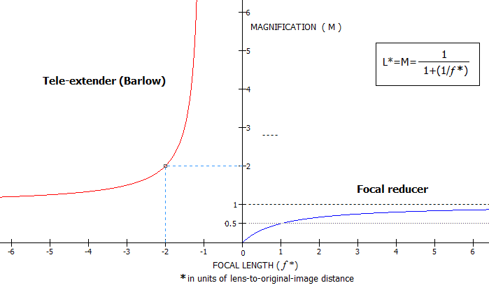
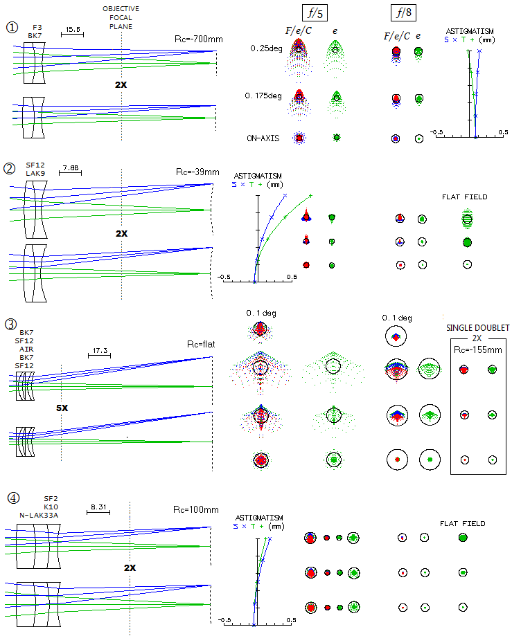
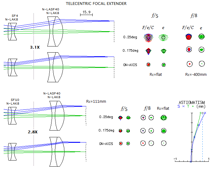
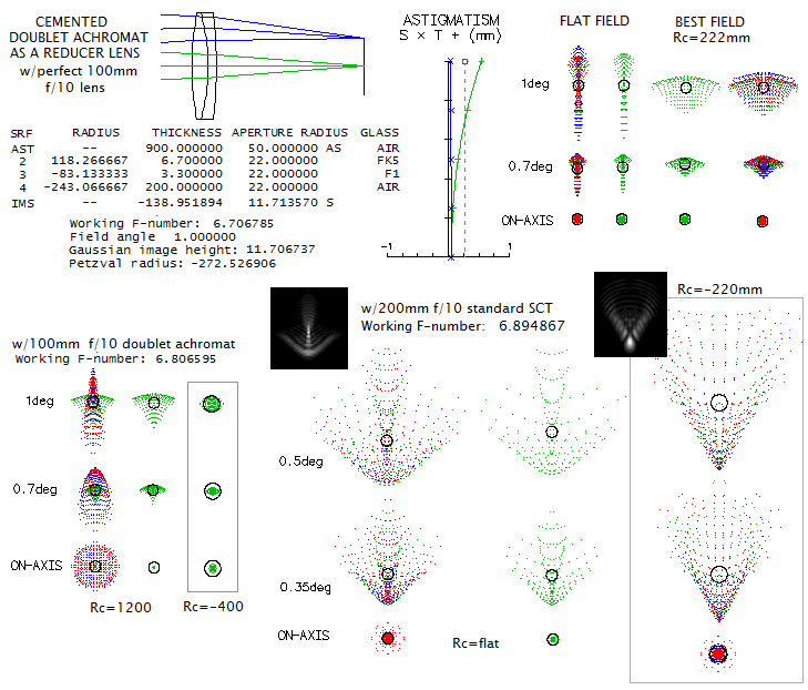
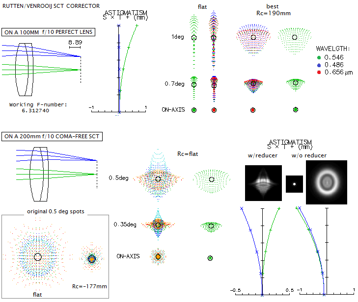
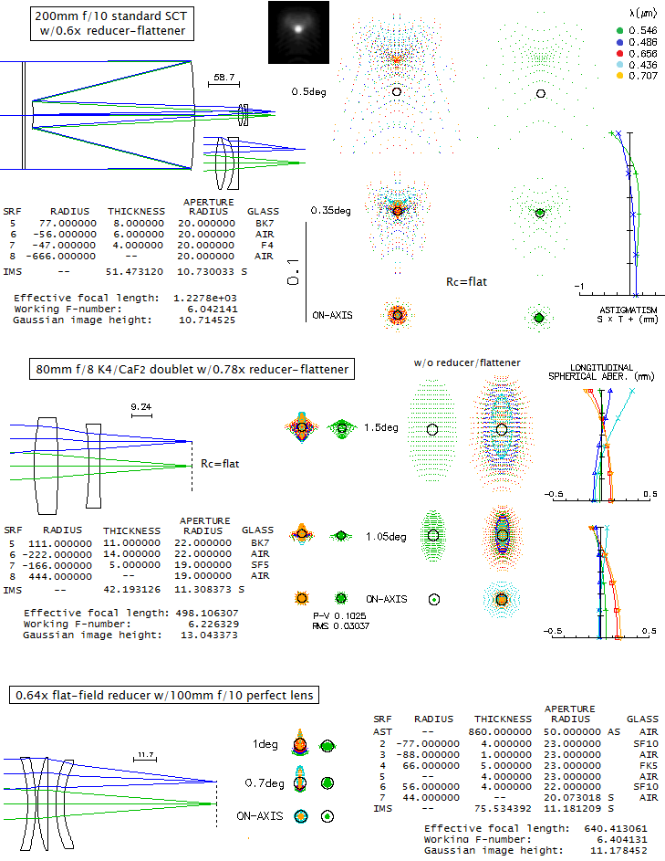
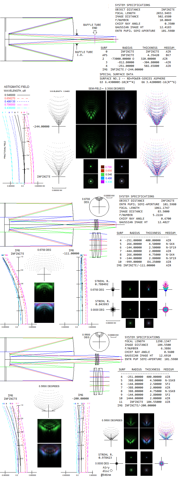
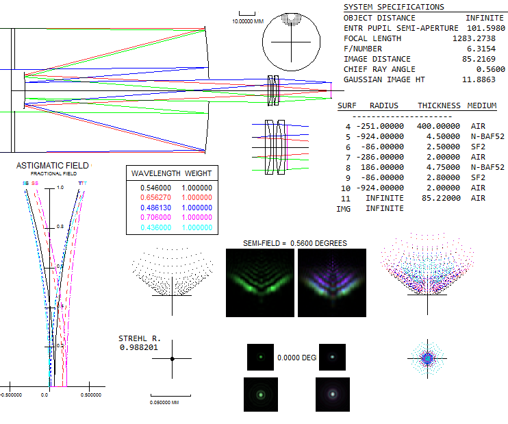
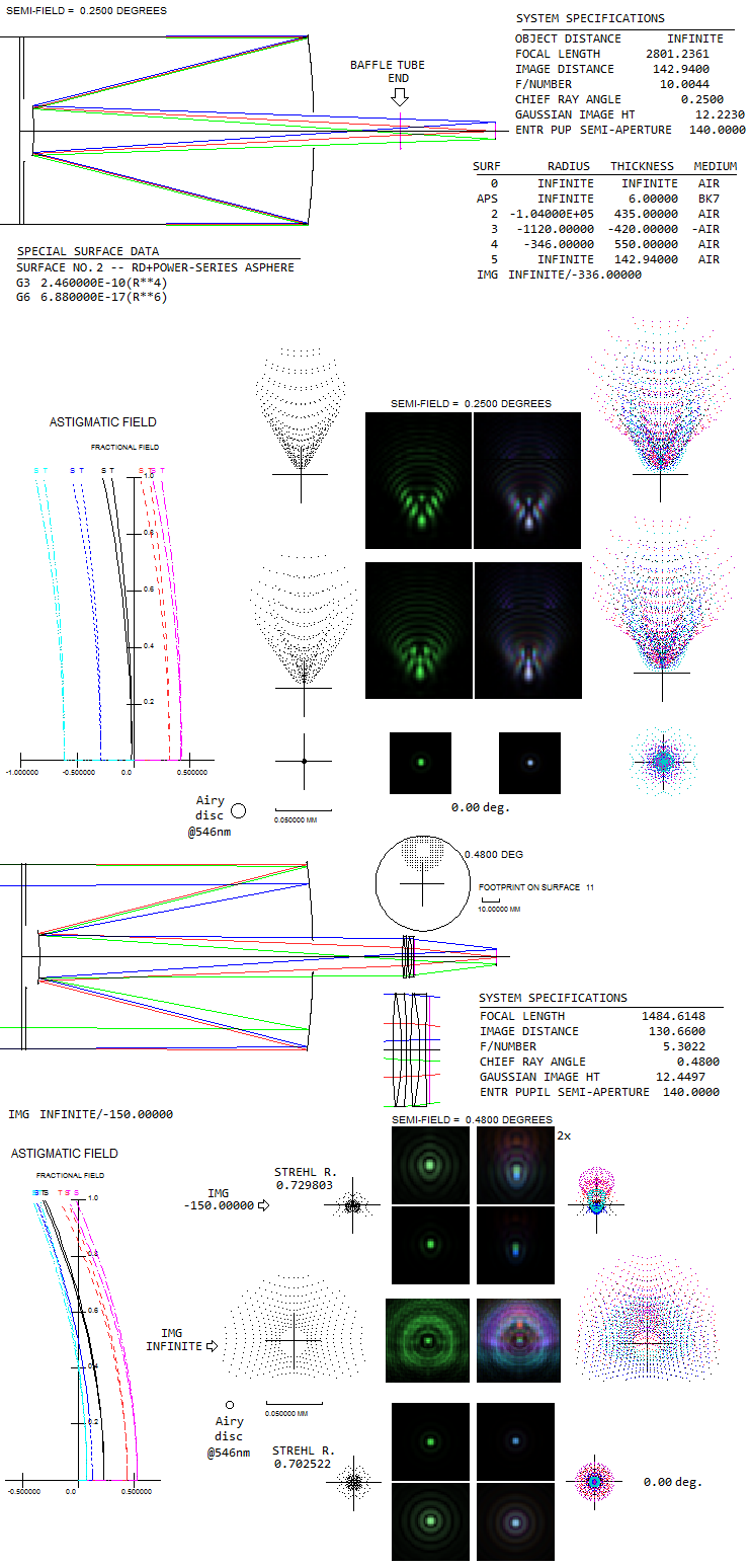
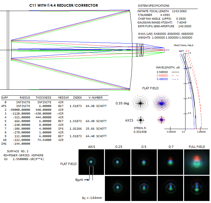
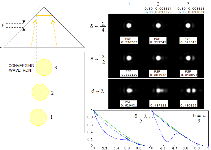
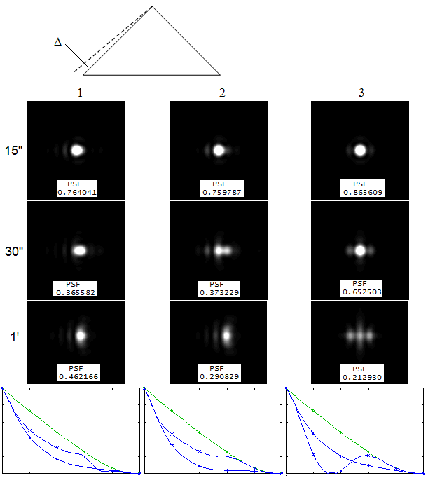
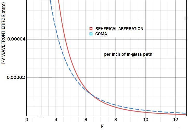


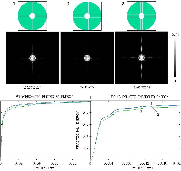

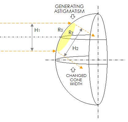 Marginal cone focusing into the final image is noticeably wider than
the axial cone, which indicates negative (barrel) distortion. Since
wider cone in effect acts as one of the faster f-ratio, it produces
smaller diffraction pattern; with the effectively shorter focal length
image magnification drops and the entire image shrinks as a result
toward field edge (black square around red grid representing the image
area is the distortionless form of it, with its diagonal equal to the
field diameter). Nominally, distortion nears 25%. Illustration at left
shows how a beam of light passing through a lens surface generates
astigmatism: the two radii perpendicular in the centre of wavefront
footprint are different, creating astigmatic wavefront deformation.
It also shows how refracted beam changes its width, increasing
vertically when it travels from left to right (shown), or decreasing
when traveling in the opposite direction (for clarity, refraction
difference between the two rays is
neglected - they remain nearly parallel after refraction, as they
do when a section of lens surface is small enough to be nearly flat).
