|
telescopeѲptics.net
▪
▪
▪
▪
▪▪▪▪
▪
▪
▪
▪
▪
▪
▪
▪
▪ CONTENTS ◄ 14.2. ATM telescopes ▐ 14.4. Commercial telescopes ► 14.3.RAYTRACING OBSERVATORY TELESCOPES
PAGE HIGHLIGHTS
Unlike amateur telescopes, used for both, visual and photography,
observatory telescopes - and the subject here are those used in the
visual range of the spectrum - are generally used for photographic work. They
range in sizes from fraction of a meter to eight meters, or more
(segmented mirrors) in diameter. All large telescopes are based on
the reflecting systems, and those sub-meter can be both, reflecting and catadioptric; very few refractors are still in observatory use. Specific
uses of these telescopes vary just as much: there is an immense amount
of information coming from the Universe, and with all our observatory
arsenal, we are barely scratching the surface.
Since they are a part of professional operation, observatory telescopes
are not only larger, but also generally more sophisticated and
technologically advanced. As such, they are a special breed, puzzling
and interesting not only to amateur astronomers, but also to people at
large.
This should open a small window into the realm of big professional
telescopes, seeking to find the truth of our Universe, and our place in
it.
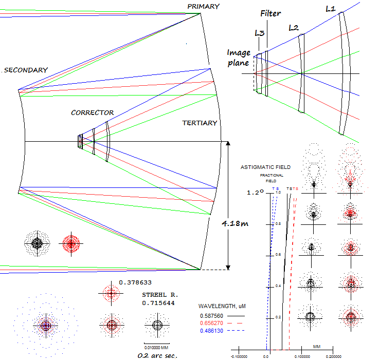
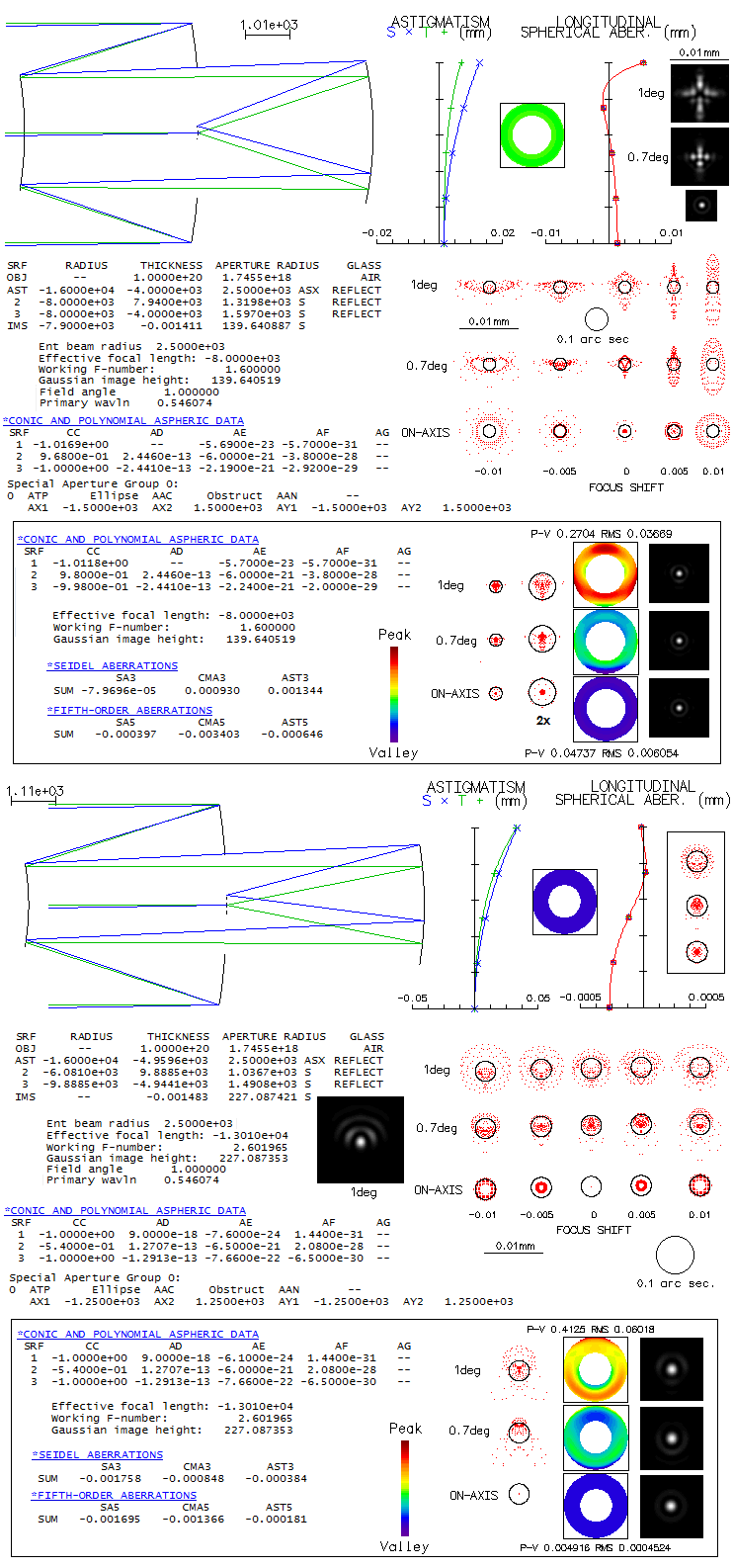
Arguably one of the best corrected simple systems is the three-mirror
system known as Paul, or Paul-Baker telescope.
So when a group of astronomers from the University of Arizona's Steward
Observatory were looking for a very large, ultra-fast widefield design
for the Dark Matter Telescope project, it led them to the Paul-Baker,
since no two-mirror system, or a Schmidt-like telescope, could achieve
the needed level of correction. The telescope would be limited only by
atmospheric seeing and sky background photon noise, which means it has
to produce star images smaller than 0.5 arc seconds, achievable
occasionally with large telescopes on best sites. The goal was the
largest telescope possible with 10m focal length, needed for sufficient
sampling with a 15-micron pixel (1 arc second=51 micron).
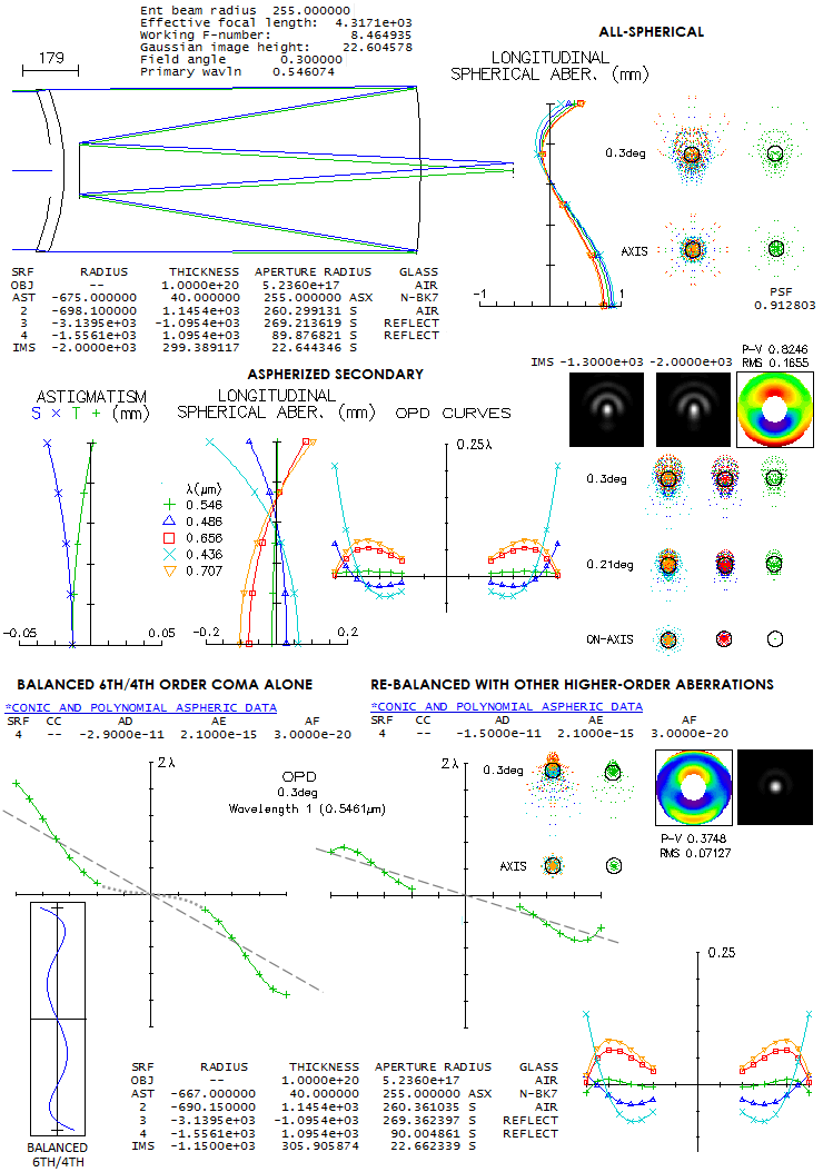
Their first design, a 6.5m f/1 Paul-Baker telescope with all three
mirrors aspherized in Zemax, was capable of producing required image,
but had suboptimal plate scale, and unacceptable chromatism from the
dewar window. That led to the revised design, a 8.4m f/1.25 telescope
with a curved dewar window and added correcting lens. This design was
the starting point for the 8.4m f/1.234 Rubin Observatory Simonyi Survey
Telescope (El Penon, Cerro Pachon, Chile), with even wider, 3.5-degree
field, and a bit better correction (less than 0.3 vs. less than 1/3 arc
seconds design image). Since there is no prescription for the Rubin
telescope, the University of Arizona's design
will be used to illustrate
this, we could say unique kind of a telescope. Unfortunately, prescription
given in the paper isn't working, but a system with comparable
performance can be reconstructed from it.
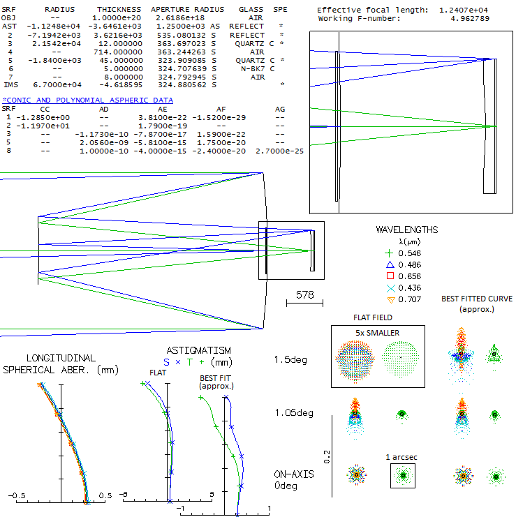
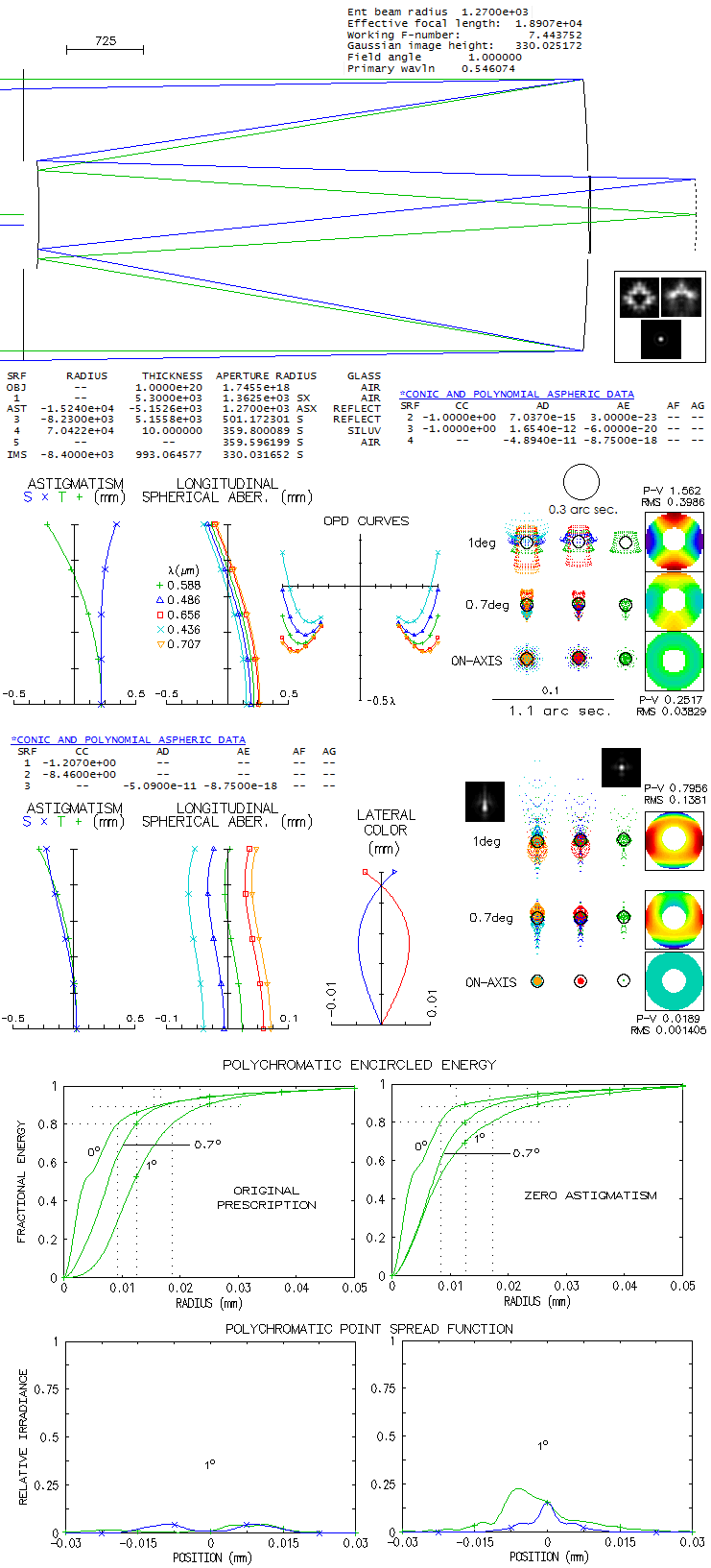
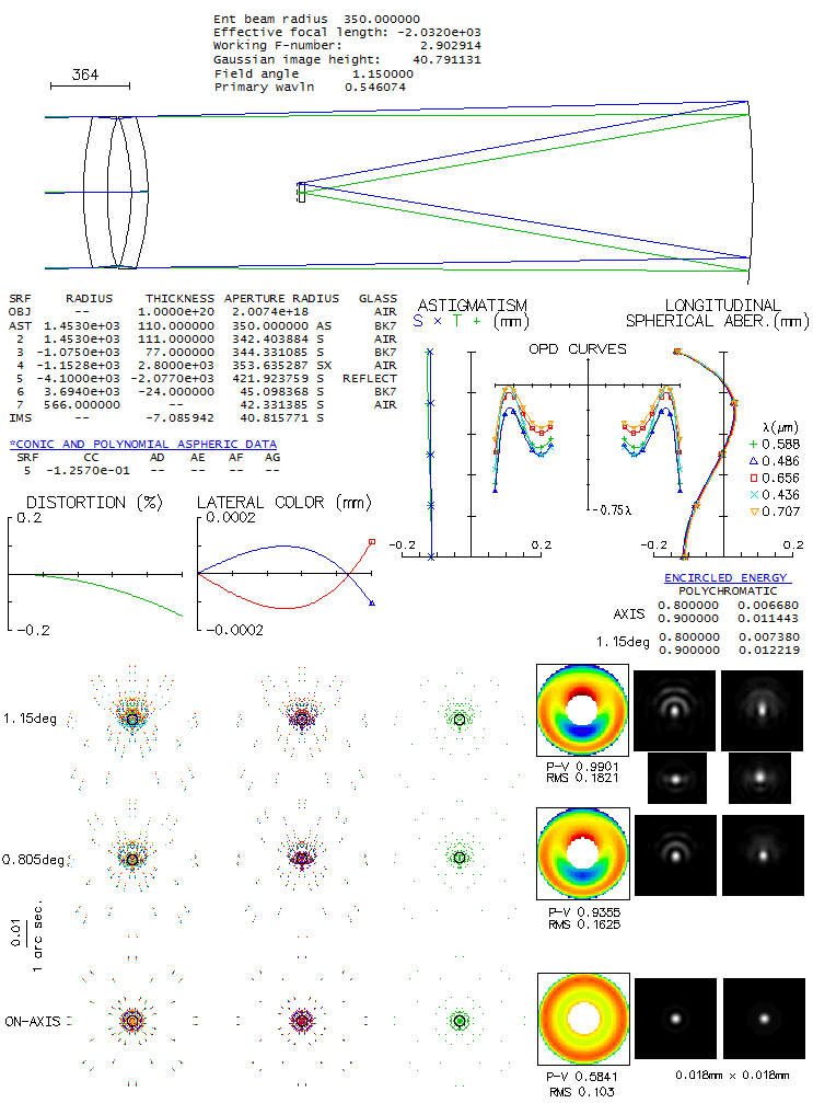
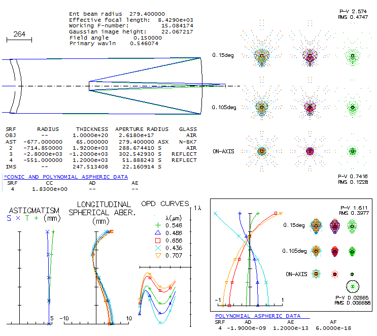
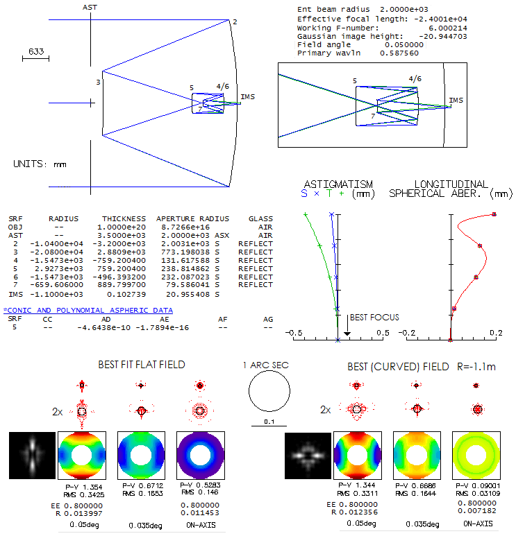
The main parameter of optical performance is ensquared energy. It is
given on the bottom of every 1-arcsec square containing ray spot plots
for the 0.80 energy square all values are in meters, so the 7.77-6
for the axial e-line 0.80 energy square is 7.77 microns). At 1.5 degrees
off axis the polychromatic 0.80 energy square side is 24.9 microns, or
nearly 0.5 arc seconds. It would probably be the subject of final
optimization, generally by near-equalizing error over the field, by
allowing more of an error in the inner field. At 1-degree off, the 0.80
energy square is 1/3 of arc second, becoming significantly better toward
axis. Astigmatism is minimized, near zero at 1.5 degrees off, with the
dominant aberration there being trefoil.
The small dot in the center of each box is the Airy disc; entirely
irrelevant here, but illustrates the magnitude of aberrations in this
highly corrected large telescope.
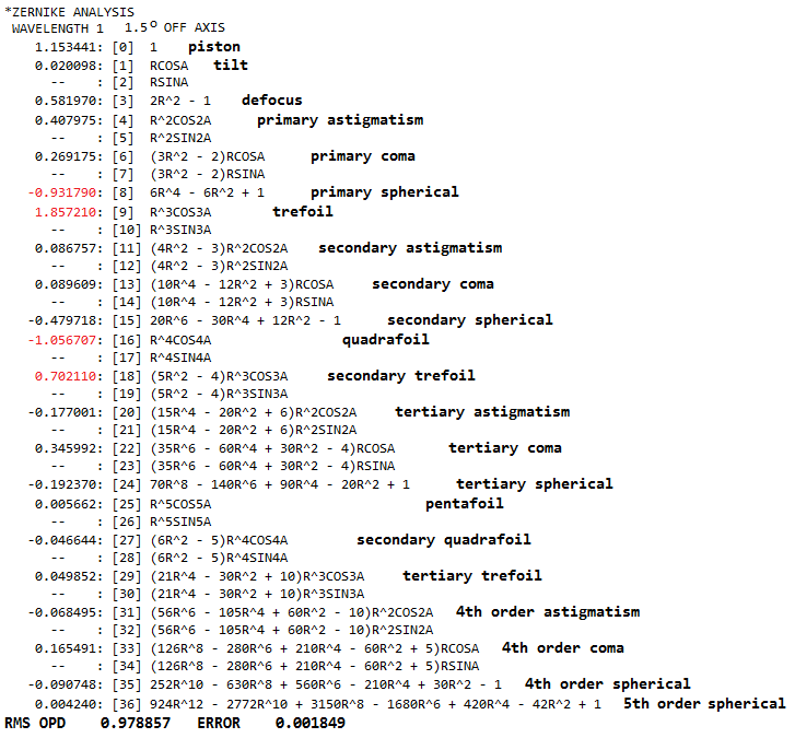
More complete picture of the aberrations is given by the Zernike terms.
The main contributors are in red (piston is not an aberration in the
single-aperture system, just a nominal artifact, and the defocus value -
which translates to 0.33 wave RMS, i.e. 1.16 wave P-V - is evident on
the astigmatism plot (best focus is not necessarily where astigmatism is
at its minimum; in the presence of other aberrations it can shift to
another location).
The largest single contributor is trefoil (#9). The next highest one,
quadrafoil (#16) is already near negligible, adding only 15% to the
trefoil (because Zernike terms add up as square root of their squared
values), and even less considering secondary trefoil (#18). Most of the
terms are negligible individually, but do have significance as a total,
creating a higher-order aberration "noise" in this large and fact
telescope.
At 1 degree off axis dominant aberration is astigmatism, but it is
significantly smaller than what the longitudinal aberration graph
indicates (nearly 6 waves P-V, from W=L/8F2, L being
the longitudinal aberration, and F the system focal ratio). The
reason is that a mix of lower- and higher-order astigmatism of opposite
signs has up to four times lower error at the best focus for given
longitudinal aberration, and that large central obstruction also lowers
the error.
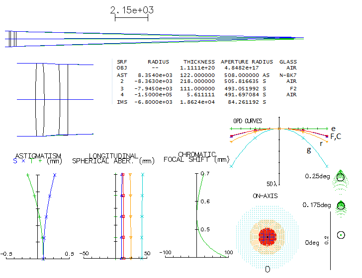
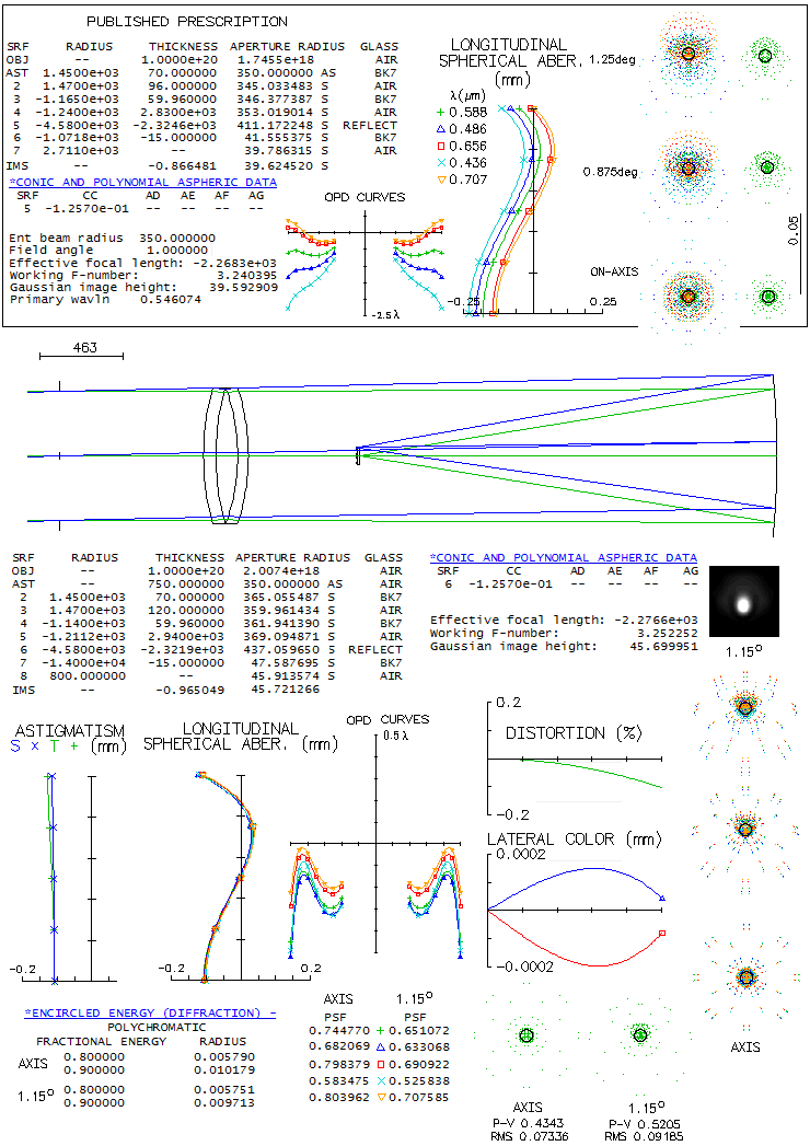
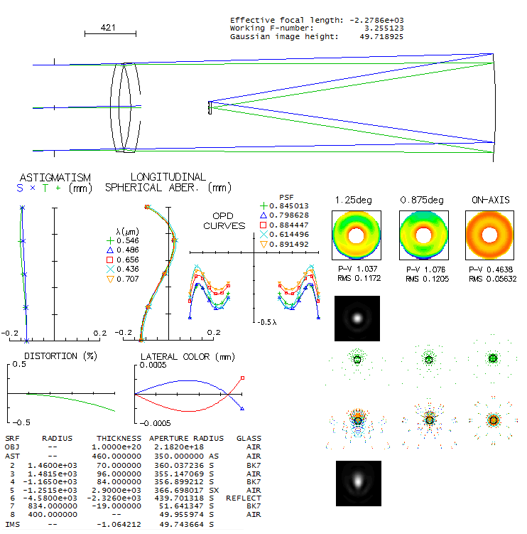
Located at Apache Point Observatory in New Mexico, the main tool of the
Sloan Digital Sky Survay project, this telescope uses a two aspheric
lens field correctors to achieve a well-corrected 3-degree field. As described
in paper by Gunn et al.
its second corrector lens is interchangeable, allowing it to be
optimized for camera and spectroscopic mode. It is used to map the
depths of our Universe.
The two corrector lenses have their radii given indirectly, through the
value of a2 coefficient, whose full expression is
a2=d2/R[1+(1-K)(d/R)2],
with d being the the surface radial height, R the
radius of curvature and K the surface conic.
It is not clear why, because the surfaces are spherical (K=0), and (d/R)2
is negligibly small, especially for the first corrector, hence for all
practical purposes a2=d2/2R, and R could be
expressed directly (for the second corrector, it would give about 3%
longer radius, but it would have little consequence).
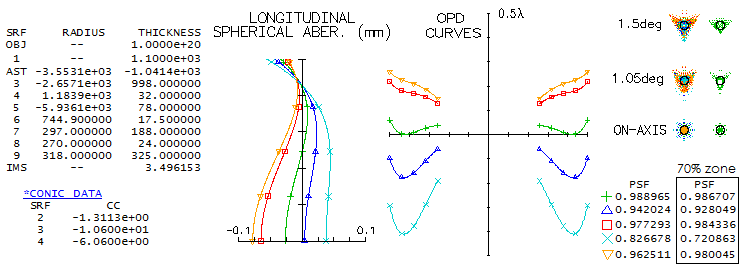
Raytracing the prescription for camera mode shows, perhaps, less than
expected correction-wise. The field is, as described in paper, nearly
flat up to about 80% of the 1.5-degree radius, curving inward rather
strongly after that. Color correction is good overall, but widely
separated lines show significantly different forms of aberrations toward
field edge, i.e. their best foci do not coincide. One of the
requirements was near-zero distortion; according to OSLO, it just
exceeds 0.1% at the field edge.
The outer portion of the field required adjustment of the detector
shape. It cannot be fitted with a near-spherical curve, and requires
higher order aspherics. Here, the asherics are combined with 67m
curvature, which resulted in a good, but still someone uneven fit (the
edge is for the best green focus; the red becomes roughly round at 99m
curvature, but green out of best focus).
The paper gives no specific performance criteria for the camera mode.
Final images were calculated as convolved with 0.8 arc seconds seeing
FWHM, which proved to be too optimistic. For the system focal length,
one arsecond is 60 microns. On the fitted field, the green line 80%
energy square is 18.7 microns on axis, 15.5 microns at 1-degree, and
35.8 microns at 1.5. It indicates that the seeing is limiting factor,
rather than optics.
Full spectral range of the telescope is 0.3-1 micron, but the familiar
visual 0.43-0.70 range well illustrates its chromatic correction.
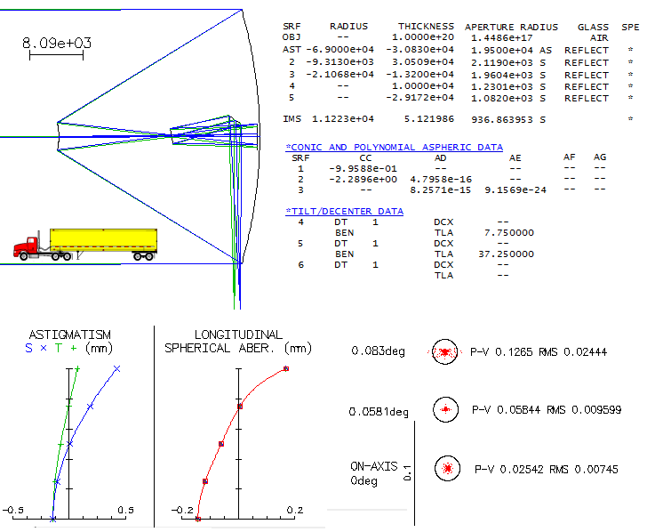
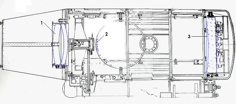
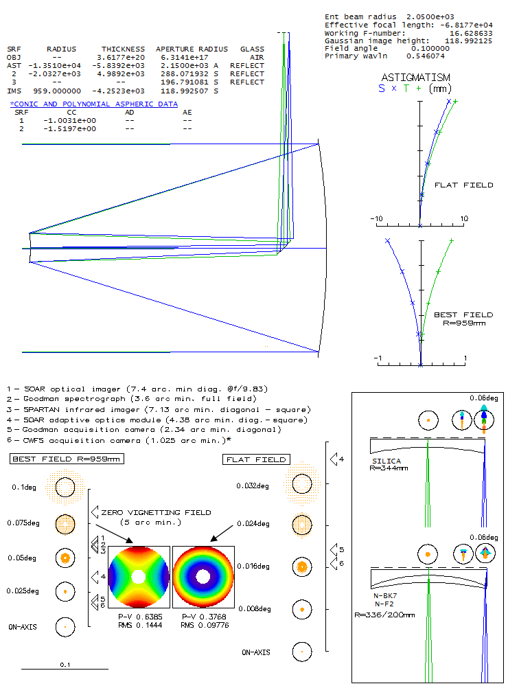
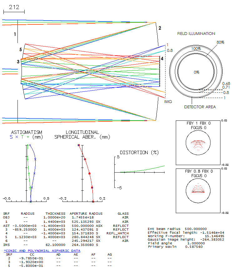
European Extremely Large Telescope is designed as a three-mirror
anastigmtic aplanat. As described in a paper by Cayrel, the 39-meter
f/0.93 ellipsoidal primary consists of 798 hexagonal segments, each
1.45m across. The 4.2m convex secondary and 4m concave tertiary are each
a thin meniscus. All three mirrors are active: the primary to make
possible for it to conform to the proper shape, and the other two -
particularly tertiary - to correct wavefront errors, mainly those caused
by atmospheric turbulence, but also those caused by mechanical
deformations.
Two folding flat mirrors direct light beam to the side (Nasmyt focus).
The first, 2.5m in diameter, is also active, "specified
to deliver near infrared diffraction limited images with over 70%
Strehl
ratio in median
atmospheric conditions (0.85 arcsecond seeing, t0
of 2.5ms)". The second flat, 2.2 by 2.7m, corrects for tip-tilt
errors.
Field radius is nearly 5 arc minutes, limited by the central hole in the
fourth mirror (even such a small angular radius produces almost 1m image
radius). The prescription gives a final f/16.6 system, somewhat faster
than f/17.5 cited in the paper; not sure what is causing the difference,
but the design correction level is very high.
Even at the field edge, correction is still at the level of 1/12 wave
P-V of lower order spherical aberration. With the ~660m focal length,
one arc second at the detector is whooping 320 microns - about 1/3 mm.
The only significant aberration is field curvature
(ray spot plots shown are for the best image surface, of 11.2m radius;
on flat field, error at the 5 arc minutes field angle - i.e. 0.94m off center -
is as much as 30 waves P-V of defocus).
Keeping in the company of the largest - ever wondered how much
chromatism there is in the largest refractor ever built: the 40-inch
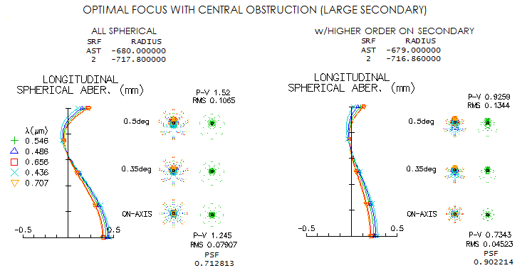
Clark refractor at the Yerkes observatory in Wisconsin? It is a common
crown/flint achromat; according to the most relaxed criterion (Sidgwick),
its focal ratio for acceptable (roughly 1/4 wave level) color
correction should be f/120 - and it is f/19. I was always
curious, just how much of color this quarter tone of achromat glass
generates. Using general data on the Clark doublet, and Barnard's
measurements, gives following picture.
On axis, Airy disc is a barely visible dot in the center of defocused
C (656nm), F(486nm), r (706nm) and g (436nm)
lines. The F/C error is nearly 7 waves P-V, which puts it at the level
of a 100mm f/1.8 achromat. At the field edge, coma is nearly three times
the Airy disc - or 0.8 waves P-V - visually unnoticeable (about f/16
paraboloid level). As a side note, Yerkes refractor
actually is not the largest ever built. It was the 48-inch (122cm)
refractor built for the Great Exhibition in Paris in 1900. It had
57m focal length (f/46.7), so it used siderostat mirror to reflect
light into immovable objective lens, with the focuser in a form of a
carriage on rails. With thermal issues and bad location on top of
that, it performed poorly and did not attract buyers. The
Yerkes refractor - the idea of George Ellery Hale, paid for by
Charles T. Yerkes and becoming a telescope in October 1897. - is
the largest ever used as a full-capacity
astronomical telescope. Now, as it
is not in use anymore, the largest used refractor is its 36-inch
f/19.3 cousin at the Lick observatory. So let's take a closer look at this
second largest refractor built by Alvan Clark & Sons.
The James
Lick Telescope was built nearly a decade before the 40-inch, in 1888.
According to a brief description by its maker, it consisted of
a biconvex crown 1734 front lens (n=1.52), and a negative meniscus
of flint 1588 (n=1.64) as the rear element (Note on the loss
of light in the 36-inch Lick objective, J.H. Moore, 1904.). Lens
radii are specified, but the separation is not, so it will be assumed as nearly
proportional to that in the Yerkes refractor (comes to ~195mm; some sources
state as little as 25mm, but it is highly unlikely, since the main
purpose of the gap was to make possible lens maitenance w/o having
to take front lens out). The lenses were exceedingly thin - 1.98 and
0.93 inch center - for a few good reasons (light transmission, weight, glass
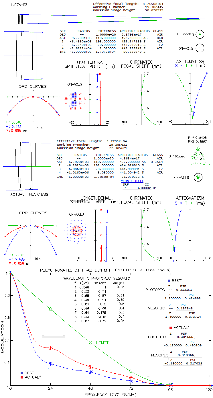
homogeneity) - but it certainly didn't help figuring accuracy. Raytrace
below uses less thickness comparable to those used in the Yerkes refractor
raytracing, but it is of little significance for the raytracing
output. First is presented such design with the standard achromat
glasses of this era, with balanced F/C aberration, corrected for coma
(top), and then the actual
objective - i.e. nearly as close to it as reasonably can come - below
(O-ZSL4 is an obsolete Ohara krown; very similar output is produced
by the Schott K3 crown).
The first, contemporary correction mode results in a defocus ranging from some 22mm at the
0.7 micron wavelength to zero in proximity of e-line and to 86mm
at 0.4 micron wavelength. In the blue (F-line) and red (C-line),
defocus is evened up at about 6 waves P-V. Monochromatic aberrations are
negligible across the field 1/3 degrees in diameter, over best image
surface of 6m radius (it is still well within "diffraction limited"
at 0.165° off flat field).
However, according to measurements,
the actual C focus of the Lick refractor is midway between its
"minimum" (i.e. optimized, 0.565 micron wavelength) and blue (F-line)
focus (On the chromatic aberration of the 36-inch refractor
of the Lick observatory, J.E. Keeler). If so, the error on the
blue spectral end becomes significantly larger, while smaller on
the red end. An MTF graph (photopic, for the e-line focus)
showing the respective contrast levels is
surprising at first: it shows significantly better contrast for
the actual correction mode, favoring the red end (nominal cutoff,
probably due to the short wavelengths lingering just above zero, is
significantly higher than the practical cutoff, which is somewhere
around 100cpm). However, it is not
too hard to see that it results from the significantly lower photopic
sensitivity to the blue/violet end. Also, with achromats generating
significant secondary spectrum, best diffraction focus is always
shifted from the optimized focus. In this case, the shift is much
more significant with the first, balanced correction mode, but
even at the best photopic focus its polychromatic Strehl is still
somewhat lower than for the Clark's lens: 0.455 vs. 0.490 (focus
shift in mm is under "Z"; zero focus shift represents the e-line focus).
For the complete picture, however, both lenses also have to be
measured against mesopic sensitivity, since during night time
observing eye sensitivity shifts toward that mode. While there
is no accurate data on the actual mesopic mode sensitivity (the
official version merely takes the average between photopic and
scotopic), it can be approximated from experimental studies. The
sensitivity is, in general, higher on both ends of visual spectrum
(and lower for the photopic peak), but more so on the blue/violet
end. The result is that the balanced mode now have higher mesopic
poly-Strehl than the Clark's lens: 0.374 vs. 0.317. It indicates
that the actual Lick refractor lens performs better with eye in
photopic mode, but becomes inferior in the mesopic mode. This
level of chromatism is roughly comparable to that in a 100mm f/3
achromat.
With respect to monochromatic aberrations, the original lens
had sigificant spherical aberration residual (reportedly, about
two waves P-V), and had its front surface aspherized at a later time
in order to
have it corrected. This arrangement (Clark's radii prescription
with the glasses closely matched) has, if all-spherical, 1.5 waves
P-V of overcorrection. It could be corrected by changing R3 to
-6295mm, but it would throw color correction out of balance
(blue F-line focusing about 2mm before e-line, and the red C-line
19mm beyond e-line focus), so it would require regrinding/repolishing of at least
one more surface. Aspherization of the front surface is much
simpler, in this case requiring 0.32 conic (oblate ellipsoid).
In his book "New serial telescopes and accessories"
(2014), Klevtsov gives prescription obtained from the Slovakian
observatory, as a big-scale example of a telescope of the Klevtsov type.
The telescope was made in Odessa, SSSR. Original prescription is with
BK7 glass (i.e. K8, its LZOS analog), but K7 glass reduces longitudinal error in the blue/violet to
less than half, so that this 1-m telescope easily passes the "true apo"
requirement. As with every system of this type, dominant aberration is
off axis astigmatism.
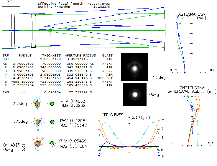
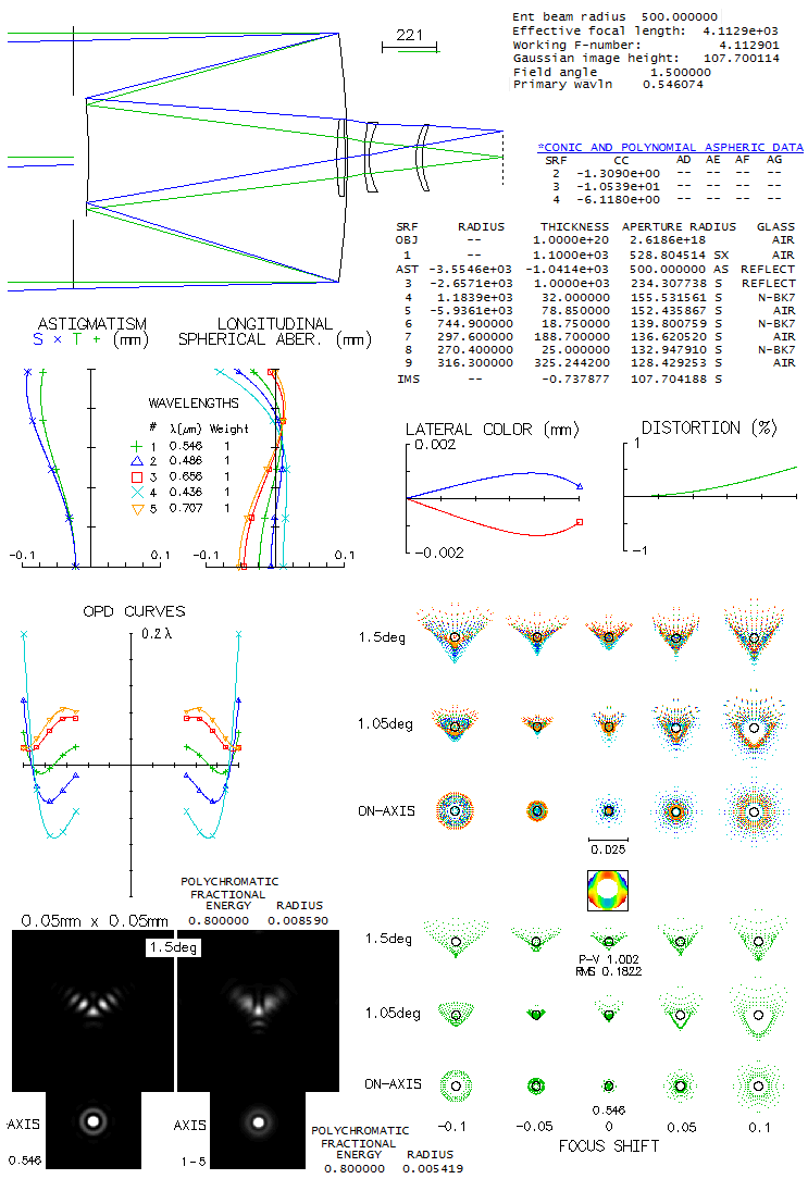
One of many designs of Valery Terebizh, the Russian "master designer" as
referred to by M.R. Ackerman, is a simple Richter-Slevogt (known as
Houghton on the Western side) modification with widely separated
corrector lenses, making possible
significantly wider fields. Survey telescopes are usually of relatively
small apertures, with large corrected field being the primary concern,
but larger apertures can be needed for detecting fainter targets.
The Houghton-Terebizh offers 5-degree field at f/3.2. The system shown
is slightly tweaked to have the axial error minimized (at no expense to
off axis performance).
Color correction even at this aperture size and relative aperture
passes the "true apo" criterion. The 80% energy square is 6.6 microns on
axis, and 8 microns at 2.5 degrees off (diffraction images are for the 5
wavelengths with even sensitivity).
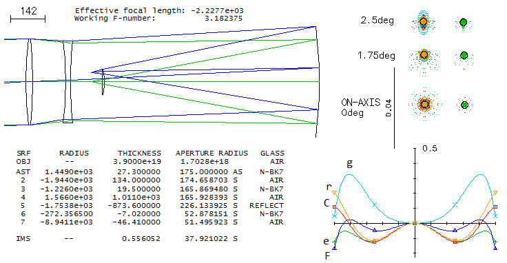
This design can also be used as a typical survey telescope, smaller in
size and faster. If rescaled to 350mm aperture and f/2.4 focal ratio -
parameters of a telescope of this design used in the gamma-ray burst
system observatory near Moscow, Russia (The Mobile Astronomical System of Telescope-Robot)
- it still preserves a very satisfactory performance.
Note that the actual telescope is somewhat shorter, with the corrector
lenses more widely separated and with the final image that would form
behind the rear corrector lens, if not directed to the side with a
diagonal flat).
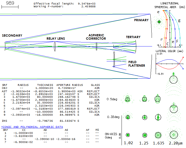
While designed for work outside the visual spectrum, the UKIRT is based
on unusual relay lens design which, with minor adjustments, could be
used in the visual range as well. Here is presented its Wide Field
Camera mode, as described in this online paper.
System is simplified by omitting optical window and filters, which has a
minor influence on its output. The entire field covers 0.93-degree
diameter, but the actually used are only four rectangular portions of
it, as illustrated in the paper. The telescope is optimized to operate
in four IR ranges: Y (0.97-1.07 microns), J (1.17-1.33), H(1.49-1.78)
and K(2.03-2.37). As given here, the is somewhat biased toward the lower
three, possibly the consequence of omitting mentioned elements.
Sub-aperture aspheric plate helps correct not only spherical aberration,
but also coma and astigmatism.
The ray spot plots are given for the central line of each of the four
wavebands, when refocused to their respective best focus. Above right
are plots for this same system in the visual wavelengths (focused on
e-line). Only minor optimization is needed to have it perform
satisfactory as a visual telescope.
The Large Synoptic Survey Telescope (LSST), a compact version of
the 8.4m telescope on the top of this page, is one of a kind, in that
it sports etendue - as a product of its clear aperture and field area -
of 318m2deg2, over 50 times more than the first next
contender. Located on the Cerro Pachon, Chile (60 miles from La Serena), this
modified Paul-Baker, or Laux telescope uses three mirrors and a 3-lens
corrector to produce a 3.5-degree field diameter with less than 0.2 arc seconds
(0.01mm) FWHM star images over its 0.63m diameter detector, with over 3 billion
10-micron pixels. In 5 spectral bands from 400-1030nm it will be used to
create by far the most complete picture of the solar system, Milky way
and transient optical sky, as well as for exploring dark energy and dark matter.
Based on the published prescription (LSST Camera Optics, Olivier et al, 2006),
I raytraced design with SYNOPSYS (free edition). Despite the prescription being
unclear in some istances - namely, not specifying front radius of the second
lens, what is the filter substrate, and to which surface of the second and third
lens were applied given conics and higher order aspherics, the assumed choices -
flat 2nd lens front surface, aspherics on the front radius of the 2nd and 3rd lens,
filter made of BK7 glass - produced performance level sufficiently close to the
description (the only change was in the value of the 6th order aspheric coefficient
on the second lens front radius, to 1e-19). It is possible that some other choices
would work better.
The field is limited to 1.2-degree radius, when definition begins to
deteriorate; but even at 1.75° the condensed core of the roughly four
times longer blur (the width is about 0.025mm) is about 0.02mm long by
0.007mm wide, or 0.4 by 0.14 arc seconds. No effort has been made to optimize
either axial or edge performance, but there is certainly room for it.
Should be noted that this particular setup is optimized for R-bend
(red); the blue line is given only to illustrate the overall correction
in this particular mode;
in its optimized setup, it is further corrected by filter shape
and small changes in lens spacing, and should be at the similar level as the red.
Despite the prescription being optimized for the red, this take on it still has
better correction in the d-line (despite the red blur appearing somewhat
smaller, it is more compact, and significantly larger than the dense core
of the d-line ray spot, as better show spots above with twice as many rays;
note that the ray spot size for highly obstructed aperture is significantly
larger than for unobstructed one, for any given level of spherical aberration).
This version of SYNOPSYS doesn't give encircled energy, which would be the best
measure for verifying the actual energy spread at any field point, but the
size of ray spot plots does confirm, qualitatively, that the field is
corrected to FWHM better than 0.2 arc seconds (0.01mm). Another useful indicator
of performance level, MTF, shows that better part of the contrast loss
comes from the aberrations in the low frequency range, and from the 0.60D
central obstruction in the mid-frequency range. In the high frequency range, the
telescope performs
slightly better than perfect aperture (MTF plot for 1° off axis roughly coincides with
the axial plot). The actual MTF, however, is obtained by multiplying the system
MTF with the pixel MTF. Since the 10-micron pixel here is somewhat larger than
the FWHM in absence of seeing error, the actual MTF would be lower approximately by a
sin(νπ)/νπ factor, with "ν" being the MTF frequency. Since
this large aperture even on the best sites will have a substantial seeing-induced
error, the pixel MTF degradation factor will likely be superseded by seeing (i.e.
the seeing FWHM will be significantly larger than the pixel, reducing pixel
MTF degradation to negligible).
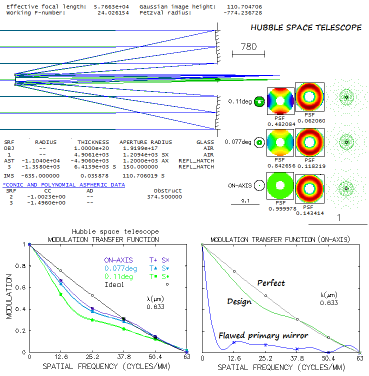
As NASA brings our space eye back to life, it warrants taking another look at it.
This 2.4m f/24 Ritchey-Chretien system could, with only two perfect conic
surfaces, achieve perfect axial corection. The real instrument, after
accounting for non-figure errors (i.e. smaller than 1/10 of the mirror diameter),
as well as <0.01 arc second pointing error, expected to deliver
1/20 wave axial RMS, or better. Off axis, limiting aberrations are 0.63m field
curvature and astigmatism, with the latter limiting "diffraction-limited" (0.80 Strehl)
field radius to 4.8 arc minutes (81mm).
Due to testing errors, HST was sent to space with incorrectly figured
primary mirror: it was a hyperboloid 2200 nanometers shallower than what
it was supposed to be (in terms of mirror conic, -1.0137 instead of -1.0023).
The four-wave surface error translates into twice larger error
at the paraxial focus, but at the best focus location it diminishes fourfold,
to "only" two waves P-V wavefront error of spherical aberration (picture below;
note different scales for the flawed and design ray plot spots). While not making the telescope
useless - even in 0.5 arc second seeing the seeing-induced long exposure
error would have been larger - but it was taking away most of the atmosphere-free
environment advantage. Lackily, the error was correctable: all it took was a
pair of small, coin-size mirrors placed close to the focal plane of each of the
instruments (the first is a plain tilted sphere, reflecting light to the actual
corrective mirror with appropriate aspheric, as well as apropriate shape to correct
for tilt-induced astigmatism, reflecting light back toward instrument).
While the secondary size needed to fully illuminate the field is only
1/8 of the aperture diameter (D), the effective central obstruction is
around 0.31D, needed for proper baffling. MTF graphs show the effect of
field astigmatism (left) and figuring error (right) for the base
wavelength.
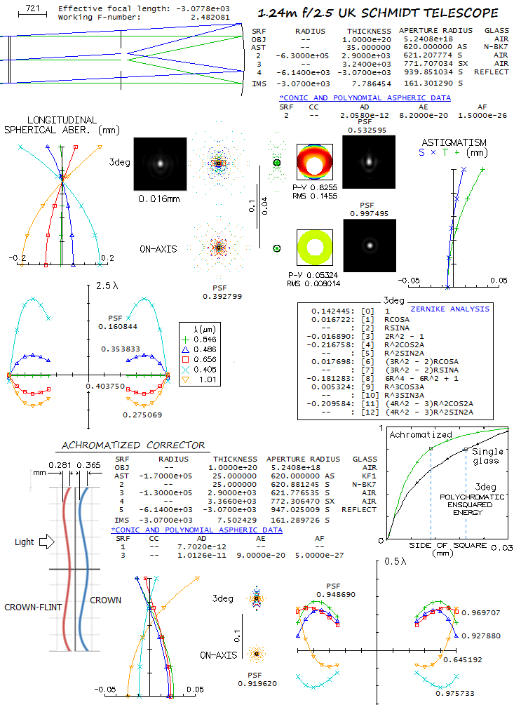
This headline is a bit misleading, because this instrument is not in the
U.K. - it's at the Siding Spring Observatory, New South Wales, Australia - nor
it is a telescope. While meter-classs professional telescopes are never used
for visual observations, they do have accessible image and could, technically,
use eyepieces. The UKST, as all Schmidt "telescopes", can't - it is a camera.
It is a younger cousin to the Oschin Schmidt "telescope" at the Palomar
Observatory, U.S. They are nearly identical in all respects, except that
the Oschin Schmidt started out (1948) with a single-glass corrector,
replaced with achromatized one in the mid-80s, and its original photographic
plate detector was replaced with CCD. On the other hand, UKST had achromatized
Schmidt corrector from the get go in 1973. and kept ist photographic plate
detectors; from the 2001th on, it was used mainly for multi-object spectroscopy
and radial velocity measurements.
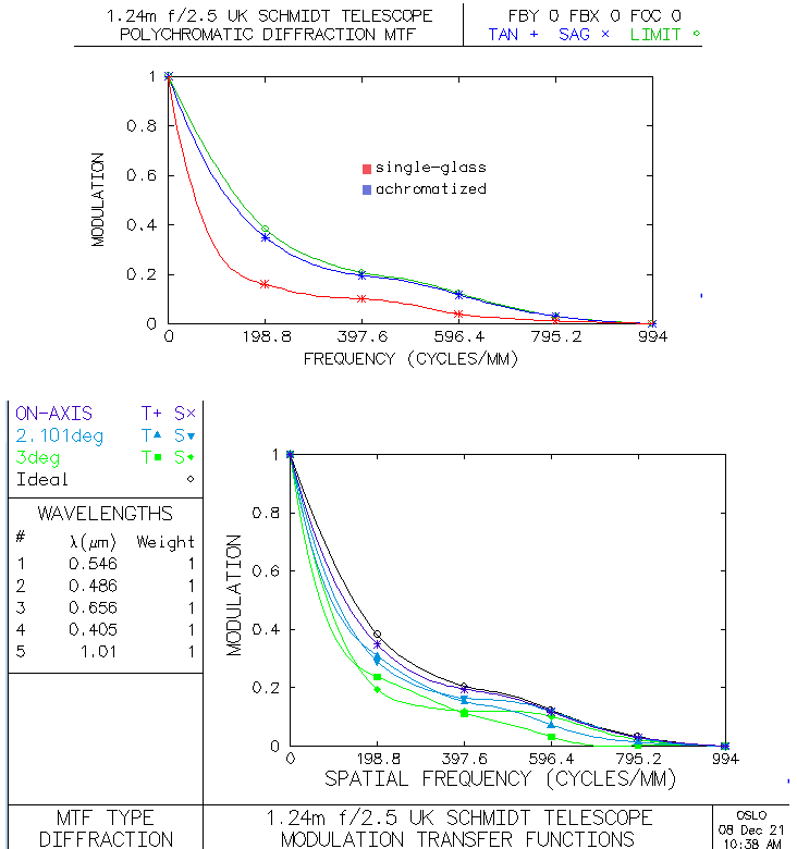
The UKST covers field of 6.5x6.5 degrees, which requires 1.9m mirror for
zero vignetting (the actual mirror is 1.83m in diameter). Below is what
its performance looks like in raytracing, for the single-glass corrector (top)
and achromatized one. I didn't find what glass combination was used for the
latter, and relied on the achromatic Schmidt coverage in Schroeder's "Astronomical
Optics". Given is the one that worked the best, even if KF1 (Schott) is
obsolete now, because the corrector is not fully optimized, and the other
possible combinations - for instance BALF4/BK7 or NSL36/BSL7 - are close behind.
Also, based on the size of the field, central obstruction is approximated
at 0.6m in diameter; the actual one shouldn't be significantly different.
At 3° off axis, Zernike analysis for the single-glass system (top)
shows only three significant aberrations:
primary astigmatism (4), primary spherical aberration (8) and secondary
astigmatism (11). However, the first two are not the actual aberrations. This
configuration is free of primary aberrations, except field curvature. The
"primary astigmatism" is actually a secondary aberration that has identical
form, but increases with the 4th power of the field height (lateral
astigmatism). Likewise, the "primary spherical" is a secondary aberration,
identical in form, that increases with the square of field height (lateral
spherical). Obviously, if we have less than 0.01 wave RMS of
primary spherical on axis, we can't have 0.081 wave RMS of it at 3° off (as
determined by the Zernike term value, 0.181, divided for primary spherical
by 50.5).
Achromitezed corrector (bottom) significantly improves performance level.
Polychromatic Strehl jumps from 0.39 to 0.92 (400-1000nm, even sensitivity),
and the square with 80% energy at 3° off axis drops from 0.02mm to 0.011mm (0.74 arcsec;
0.5 and 1.3 arcsec on axis, for the achromatized and single-glass, respectively). This directly
determines both, limiting resolution and contrast transfer efficiency. However,
achromatized corrector requires significantly deeper curves: 0.281mm and 0.365mm
vs. 0.076mm for the single-glass curve (all three have point of inversion,
i.e. maximum deviation at ~0.71 zone).
Of course, these figures are valid only for zero atmospheric error, tube currents
and misalignment. The first factor is the most significant: even in 1 arcsec
seeing, this aperture is subjected to a D/r0~9 turbulence, with its
diffraction pattern broken into a speckle structure, bloated into a blur
several times the Airy disc size. In order to have its atmosphere-free
PSF maxima still intact, the camera would need 0.2 arcsec, or better seeing.
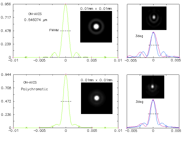
Image below shows the system PSF for achromatized corrector; due to the 0.48D central obstruction,
the central maxima diameter is about 20% reduced, and the FWHM for the e-line
little more than 7%, at less than 0.0013mm, or below 0.09 arc second (PSF simulations are in
different proportions to the graphs, and among themselves for center vs. off axis).
In 1 arcsec seeing,
the FWHM would be enlarged to roughly 0.5 arcsec - little better than FWHM of
the 8-inch aperture. PSF simulations are normalized to 0.5 intensity, thus
the bright central disc approximates the FWHM. The polychromatic FWHM is
smaller than the e-line FWHM due to wave interference; neither changes appreciably
in size at 3° off axis, although some elongation - mainly due to lateral
astigmatism - is noticeable. Either FWHM encircles less than 50% of the
energy. Atmospheric enlargement of the FWHM would significantly lower
the sytem's design contrast transfer efficiency, shown below.
The MTF shows that the effect of obstruction - determining the contrast
transfer limit (green plot) - is much more of a factor
than system aberrations with achromatized corrector (top). Transfer efficiency decreases toward
outer field, but remains effective, except for the cutoff frequency
reduction in tangential plane, due to the aforementioned FWHM elongation
(bottom, for achromatized corrector).
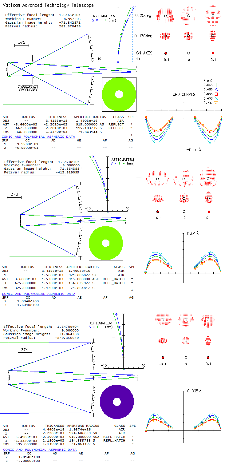
A part of the Mount Graham International Observatory, Arizona, this 1.83m with
f/1 primary is rare exception in that it employs aplanatic Gregorian two-mirror
system, instead of the usual aplanatic Cassegrain, also known as Ritchey-Chretien.
Is there something in the optical properties of its image that makes it
the favorable choice, since the compactness obviously is not its advantage?
Here's what raytrace shows.
Compared with aplanatic Cassegrain with the primary of the same focal ratio,
and with nearly identical focal length (middle), the Gregorian has slightly less curved
best image surface, and slightly less astigmatism. The Cassegrain, on the
other hand, has slightly smaller central obstruction (0.4m vs. 0.43m, as the
secondary diameter needed to fully cover 0.25° field radius, enlarged
10% as the minimum needed for the secondary housing), and 18° shorter
secondary-to-final-image separation.
But comparing the VATT with a Cassegrain of nearly identical secondary-to-final-image
separation seems more appropriate. In that case, the Cassegrain sports an f/1.5
primary, significantly more relaxed field curvature, nearly 20% lower
astigmatism and identical central obstruction (bottom). Hence, the Cassegrain
offers better overall performance level, although the difference is still small.
Interesting detail is that all-reflecting systems do have non-zero chromatism
(other than that caused by different diffraction pattern size
at different
wavelengths). In presence of spherical aberration, the magnitude of aberration is
inversely proportional to the wavelength.
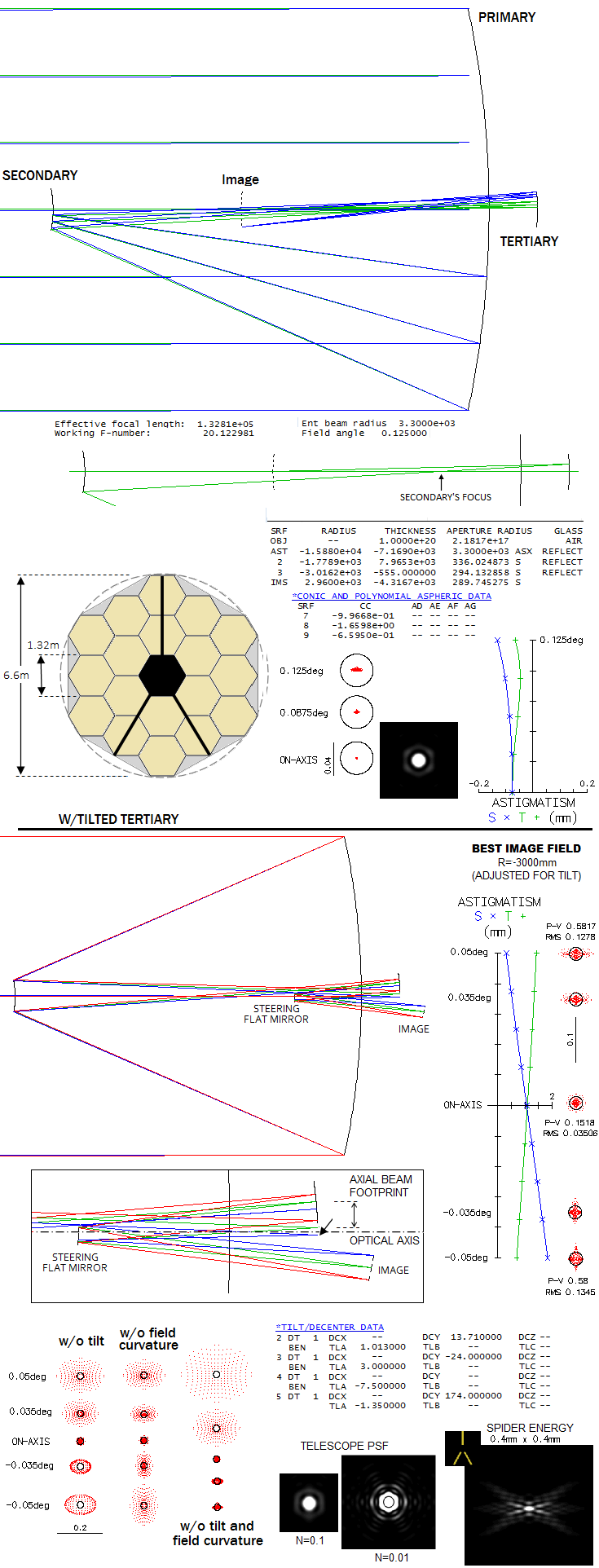
JWST came as a replacement for the Hubble Space Telescope. It is a 6.6m f/20.1
three-mirror Korsch anastigmatic aplanat. The primary is made of 18 hexagonal mirrors
forming near-paraboloidal f/1.2 ellipsoidal surface (gray area around it
fills in to the simplified shape used for the raytrace). The secondary is a
hyperboloid, and tertiary prolate ellipsoid. In order to make it more practical for use
with instrumenation chamber, the tertiary is tilted to reflect converging
light onto the flat steering mirror placing the final image behind the primary.
It will operate in a wide infrared spectrum (0.6-27 micron), with one
of primary purposes being collecting information about first light
sources in our Universe, within the first galaxies, red-shifted to
near-infrared and centered around 2 micron wavelength, at which it
should be "diffraction limited" (0.80 Strehl). Apparently, JWST already
discovered what should be the oldest known galaxy - GLASS-z13 in Ursa
Major - 13.4 billion years old (at the time it formed, it was 3 billion
light years from where we are now; light traveled 13.4 billion years
to reach us, but the distance between us today is, due to expanding
Universe, over 33 billion years). At the time it formed, Sun didn't exist,
and the galaxy probably doesn't exist now.
Image below shows the optical system, performance of the basic design (top) and
the actual design with tilted tertiary and added flat mirror (bottom). Design
data is from "James Webb Space Telescope: large deployable cryogenic
telescope in space", P.A. Lightsay et al. (prescription given there
does not contain tilt and decenter data, so the design is in that respect
approximation). Field angle shown with the basic design is somewhat
larger than in the actual telescope (up to 0.1 degree radius, judging on the
size of tertiary mirror on a system drawing) in order to
make ray paths discernible. Design correction is excellent over the best image
radius (2600mm, concave toward secondary). Over flat field though, the edge
spot bloats to 3/4 of a milimeter.
Tilting the tertiary induces strong astigmatism, much less of coma, as well as
image tilt. Here, field radius is 0.05° (3 arc minutes), which is
probably closer to the actual telescope (also, it is about the maximum for
the 3° tertiary tilt). After adjusting for image tilt and curvature,
correction level is excelent, from better than 1/8 wave P-V equivalent
of lower order spherical aberration on axis, to a little over 1/2 wave
at 1/20 degree off (minimizing spherical aberration requires slightly
lower primary conic, -0.9967). The field could be still slightly
corrected for tilt, but it wouldn't produce appreciable gains. Best
image surface radius is now -3000mm, concave toward
flat mirror. The only point image aberration is low-magnitude primary astigmatism.
Ray spot plots bottom left show what the field looks like without
corrections for tilt and field curvature. There are big discrepancies
between decenter stated in the article (0.19mm for the tertiary) and
workable values. If the tertiary is tilted, it induces very strong astigmatism
and coma; astigmatism can only be offset by tilting the secondary (which
is evident on both published drawings and raytrace presentations), while
decentering it induces coma. To have it all balanced requires also
decentering the tertiary, which also induces coma, but primarily
astigmatism. One peculiarity is that tertiary can't be centered
around axial cone; it is shifted up with respect to it (small arow
shows bottom of the blue diverging cone at the tertiary). In effect,
light falling onto it is using an off-axis section of that ellipsoid.
When the tertiary is positioned axially, minimizing astigmatism
requires decreasing its tilt angle, and that cannot be done since
it is necessary for placing the flat out of the light cone.
Note that the Airy disc shown is for 0.5876 micron wavelength, just
below the lower end of the telescope's operational spectrum. Airy
disc size changes in proportion to wavelength, so at the 2 micron
wavelength it is 3.4 times larger - with the aberration proportionally
smaller - and at 27 micron as much as 46 times larger. With the
effective focal length of nearly 133m, one arc second spans 0.64mm.
Resolving power of the aperture (neglecting central obstruction effect),
λ/D ranges from 0.0188 arc seconds at 0.6 micron wavelength
(0.0006/6600 times 57.3x60x60, to convert from radians to arc seconds),
to 0.84 arc seconds at λ=27 micron. This implies that quality
field varies significantly with the wavelength.
Simulated PSF (bottom right) show that the axial diffraction pattern, due to near-hexagonal shape
of the primary, has also hexagonal 1st bright ring; central maxima appears
slightly non-circular, but larger images show it perfectly round.
With intensity normalized to 0.01 - note that scale for these two
patterns is different - the
pattern shows low-energy regions forming hexagonal wide-spike pattern
(intensity points equal and higher than 0.01, or 1% of the central
intensity are white). Energy spread by the spider vanes, shown
as an inverse aperture, has most of the concentration in the
central maxima, roughly 1/30 mm long, two pairs of V-shaped spikes
and two elliptical spots above and below the maxima. The approximate width of
the vanes is 6 inches. Central obstruction, determined by the missing
central segment, is approximately 20% by diameter (23% when extracted
from the area).
As already mentioned, this design is approximation, since no complete
prescription was available. In the final optimization
astigmatism can be even further reduced, but the correction is already
very satisfactory. Axial correction error could be further reduced by making
the primary figure accurate to yet smaller decimals, but it is neither
necessary nor realistic (at the optimum primary conic, -0.996754, coupled
with -1.66 secondary conic to keep the coma minimized, axial correction
is 1/74 wave P-V of mainly primary astigmatism and some secondary coma, with
the error at 0.05° off axis reduced by less than 10%).
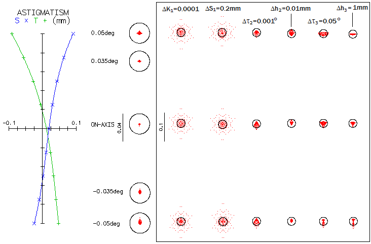
This design shows that the design limit for JWST is significantly better
than 0.80 Strehl in 2 micron wavelength, on and off axis. But fabrication is
always less than perfect, and collimation, pointing and
thermal errors cannot be entirely eliminated. Below is illustration of
the sensitivity of this system to some of the basic possible errors.
For clarity, aberrations at the system limit are further reduced (left).
It is achieved by tilting the tertiary somewhat more, to 3.15°, with
slight changes in the decenter of the secondary (13.705mm) and tertiary
(-19.7mm; putting -19.69mm brings zero astigmatism point to the field
center, but has no practical significance); optimal primary conic is -0.996755,
and -1.66 on the secondary.
Inside the box, effect of very small changes in the figure (primary) and
position of the mirrors on the ray spot plots (note that the scale is
2.5 times larger in the box; Airy disc is, as before, for 588nm wavelength).
From left, change in the
primary conic, primary-to-secondary separation, secondary tilt and decenter,
and tertiary tilt and decenter (all changes are smaller in their absolute value than the
optimum). In general, induced aberrations change
in proportion to the deviation: doubling the deviation doubles the (induced)
aberration. As little as 0.0001 deviation in the primary conic -
and that is an f/1.2 18-segment surface - induces 0.075 wave RMS
(slightly below 0.80 Strehl) of primary spherical aberration in the 588nm
wavelength; at 2 microns, it will be smaller in inverse proportion
to the wavelength, i.e. 0.022 wave RMS.
The sensitivity to the secondary tilt is not a typo: as little
as 1/1000 of a degree induces about 0.045 wave RMS (@588nm) of all-field coma.
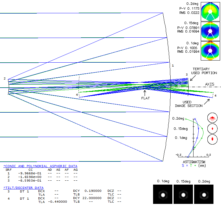
ACTUAL DESIGN - After I've put here on what appeared to be approximation of the JWST optical
design, I had a whisper to my ear (Mike Jones) telling me what the actual
design should look like. I'll keep the above system here as a tilted-mirror
alternative, but the actual design keeps them orthogonal to the axis.
Except above mentioned slight tertiary decenter - purpose of which is
to tilt the image so that the used portion becomes nearly perpendicular
to the optical axis -
there is no other perturbations in the mirrors' rotational symetry vs.
optical axis. As image below shows, the flat is centered around optical
axis, but it is not in the light path because JWST uses only off-axis
section of the image field (that's why it appears that both secondary and
tertiary are tilted). In this case, the green cone forms image point at 0.1°
off axis, and the blue cone point at 0.2°. Usable image is between 0.1 and
0.2 degree off axis.
Due to this geometry, light forming the image uses
only part of the upper half of the tertiary, with the rest being removed
to allow light reflected from the flat to form image beyond the tertiary.
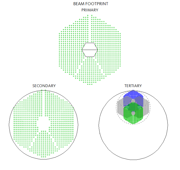
Beam footprint for the 0.1° field point at the primary (aperture
stop, 1), secondary (2) and tertiary (3) is shown below. Since aperture
stop is on the primary, any field angle has identical footprint on it.
It is differs only slightly on the secondary, while on the tertiary
all footprints fit on the upper half of it (for 0.1° field radius
on the primary and secondary, for both on the tertiary;
needed tertiary radius for zero vignetting is 398mm, and 345mm for the
secondary). The dashed circle
is the off-axis
section on the tertiary containing all beams for a circular field.
Tilt and decenter of the image are only to show its characteristics
over the used portion, when positioned optimally vs. cameras. Correction -
as the design limit - is still exsquisite (note that this is the same
astigmatic field shown above with the basic design, only expanded to
0.2° radius; in the outer field, higher-order astigmatism kicks in
causing tangential surface to cross over the sagittal). The field
could be extended
outward by manipulating astigmatism, without significant effect on the
correction level, but the limit to its size is set by the need to keep it
nearly flat. In this case, the diameter is 0.1°, or six arc minutes.
The field could also be extended toward axial cone, but no more than
one arc minut, or so (w/o vignetting).
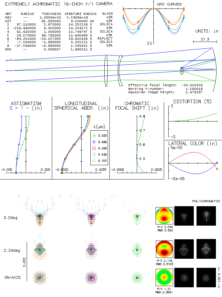
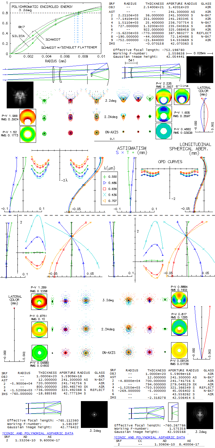
"Extremely achromatic" is how Epps and Vogt described the camera they
designed for the Keck telescope spectrometer in 1993 (Extremely
achromatic f/1 all-spherical camera constructed for the high-resolution
echelle spectrometer of the Keck telescope; drawing by Epps with the
prescription data published online is from 1990). It is probably as simple
as such a camera can be: all-spherical, consisting of a two-singlet full
aperture corrector, mirror, and a single field lens made of the same glass
as the front end corrector. Unlike the old-fashioned Schmidt/Houghton
cameras, it comes with flat
field (a comparison could be interesting). Below is how it raytraces
with OSLO Edu. As both, LA and OPD plots show, there is no longitudinal
chromatism to speak of, although the colors could be made yet little tighter
(camera was intended for 0.3-1.1 micron range - and beyond - but here it is
raytraced only for the conventional visual 0.43-0.67 micron range; obviously,
there is enough room to go toward longer wavelengths, since the red end here is
beter corrected than the central line).
The spherical aberration leftover on axis could be minimized to better
than "diffraction limited" (0.80 Strehl), but may have been left in on
purpose, in order to make the point image energy spread over the field
more even.
Field seems to be limited to less than 4° radius by departure from
flatness and higher order aberrations (in the sense that star images remain
similar in size). At 4°, trefoil becomes the dominant aberration form,
and quadrafoil becomes the third, after primary astigmatism (which
probably includes significant portion of Schwarzschild's lateral astigmatism).
Paper cites 1.8 inch (3.4°) field radius, but here it is 3.2°,
which gives more even field quality. Diffraction simulations show fairly even blurring
accross the field, with the dense blur portion well within 0.001 inch
(0.0254mm). 80% energy radius is 0.0072mm at the 70% radius,
and 0.0089mm at 4 degrees (2 and 2.4 arc seconds, respectively).
There is a discrepancy between the claimed f/1 focal ratio, and the actual
f/1.58. Aperture stop radius on the drawing is given as 9.5 inch, and the focal
length given in the abstract is 30 inch; that produces f/1.58, not f/1.
With a bit larger field, the front lens radius needed to accept
all incoming light goes to 15 inches, but it is not the aperture stop, and
the focal ratio remains f/1.58. Pulling the stop all the way back to
the font lens changes little in the magnitude of aberrations.
If the stop at this location would increase to 15 inch in radius, it
would produce a f/1 system - but it would be a different configuration,
with significantly inferior performance (although better than with
the stop expanded to a 15-inch radius at its original location).
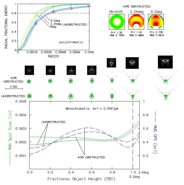
Below are ploted encircled energy (top) and RMS spot size/OPD for the
field (bottom). So far, central obstruction effect was omitted, but
it obviously cannot be avoided, and has to be relatively significant.
For 3.2° field, minimum central obstruction size, determined by
the size of field lens (for full field illumination) is about 40% linear
(image itself is about half as large). Encircled energy plots for the
five wavelengths, even sensitivity, (top left)
indicate that obstructed aperture has smaller 80% encircled energy radius
up to 70% of the field radius, but keep in mind that the starting point,
i.e. unit energy
in the obstructed aperture is over 10% smaller PSF (linearly), whose central maxima
contains less than 71% of the energy of the unobstructed central maxima
(the unmarked plots are for unobstructed aperture, with identical
color code field-height wise).
Ray spot plots for obstructed and unobstructed aperture are generally similar.
Diffraction simulations (for the actual, obstructed aperture) are about twice
larger, for clarity. Patterns
are similar to those of unobstructed aperture over most of the field,
but closer to the edge they spread wider. The RMS spot size (radius) is
generally smaller for unobstructed aperture, even on axis, due to the smaller
obstructed spot here being of even density, while the unobstructed spot has
two denser inner areas (most dense around the center), not clearly
discernible at this scale. The RMS
spot size (given as radius) is nearly constant up to 90% of field radius,
after which quickly increases, mainly due to trefoil-like deformation.
Over about 80% of field radius the RMS spot is little over 0.0002" (0.005mm, e-line) vs.
0.0126mm (diameter) cited in the paper as the whole (3.4°) field average,
making it suitable for 7-15 micron pixel chips. Diffraction images
above match this averaged RMS spot size fairly well.
This optical arrangement is simple enough to be within reach of the
advanced ATM. Scaling it down to, say, 6 inch aperture, would have
the blur size reduced by a factor of 0.4, to some 4-5 microns.
Below is described system of this kind, using BK7 glass and with
the stop at the fron lens, suitable to be used as a stand-alone camera.
Still,
at this fast focal ratio tolerances are very tight. For instance,
just 1mm shorter front field lens radius would negatively affect lateral
color correction. As mentioned before, significantly reducing stop
separation, even placing it at the front lens, would have relatively
minor consequences. As mentioned, minimum central obstruction,
due to the assembly
that would house the field lens and detector is about 40% linearly
at this field size (image itself is always significantly smaller).
To have better idea of the degree of chromatic and overall correction
of this arrangement, we'll compare to a known standard, the Schmidt camera
of the same aperture and focal ratio. Linear central obstruction
is 40% in the Ebbs-Vogt systems, and 20% Schmidts.
In addition to the above system (top left), standard Schmidt (bottom left)
and flat-field Schmidt (bottom right),
included is the above system with silica replaced with the Schott BK7,
with the stop at the front lens (stand-alone camera, top right). It compares favorably to the system
with a distant stop both, size wise, and with respect to overall correction.
In order to make chromatic correction easier to compare, both Schmidt
systems and the "short" Epps-Vogt have minimized error on axis; that
influences somewhat field correction. System drawings are nearly on the
same scale, thus directly comparable size-wise (note that the Schmidts and "short"
Epps-Vogt prescrptions are in mm).
The two Epps-Vogt systems have very similar level of chromatic
correction, but the "short" version is easier to compare to the Schmidts.
Its superiority in the axial chromatic correction is obvious immediately,
in all four non-optimized
wavelengths (note that the nominal P-V error is not representative in
obstructed systems, since measured from the non-existing vertex,
while the RMS is measured only over the annulus area). Better
overall axial
color correction for 0.3-1.1 micron range would have the blue/violet focusing
longer - as in the original design, or even more -
because yet shorter wavelengths focus shorter, and the error
on the violet end is much larger than on the infra-red.
Epps-Vogt systems have about half the lateral color of
the flat-field Schmidt, while that of the standard Schmidt is
practically non-exsistent on the given scale.
Polychromatic encircled energy (top left), however, shows that
there is not so much difference in the 80% encircled energy radius
(the five wavelengths, even sensitivity). Better chromatic correction
of the Epps-Vogt is mainly offset by the better field correction of the
Schmidt. Diffraction simulations for 3.2° field radius (polychromatic,
the five wavelengths, even sensitivity) show
significantly more difference in the intensity distribution pattern, than in
encircled energy. Note that placing stop at the front surface produces
similar type of field edge pattern in the original Epps-Vogt; for some reason,
they opted for somewhat wider, but more evenly mixed color-wise spread
toward field edge, even at the price of a widely separated stop (some
stop separation is inevitable with spectrographs since the camera has
to be preceded by the collimator and dispersive element). The
coma-like ray spot plot is actually produced by a wavefront deformation
closer to astigmatism; as the wavefront maps show, it affects a narrow
outside wavefront side strips, mainly on the bottom half, with the edge
wrinkle spreading to the bottom, and becoming nominally larger
toward shorter wavelengths. The relative area of deformation is
quite small, and so is the amount of energy spread out.
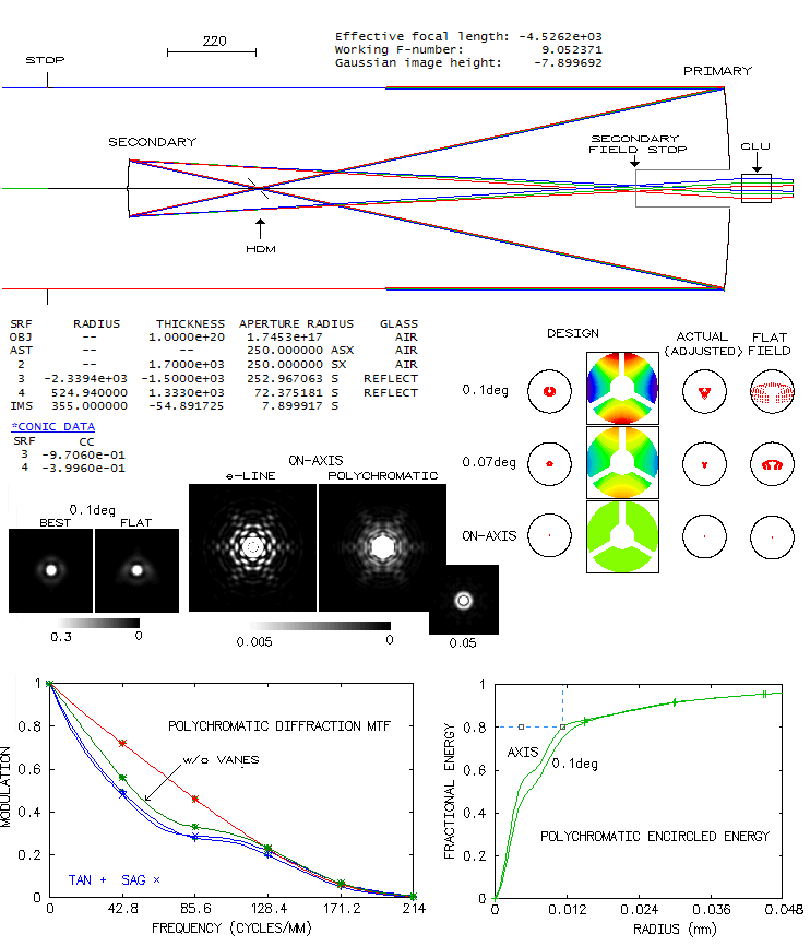
Described as "the largest state-of-the-art solar telescope (...) ever
completed and flown in space" (The Solar Optical Telescope of
Solar-B (Hinode): The Optical Telescope Assembly, Suematsu et al.
2008), it was designed for high-precision photometric and polarimetric
observations of the Sun in the visible spectrum (388-668nm). Placed
out of the atmosphere - Solar-B satellite, later renamed to Hinode -
it is capable of resolving magnetized structures down to 0.2 arc seconds,
out of reach of ground based telescopes. This requirement was the
main factor determining the aperture size. The system can be
separated into two components: (1) Optical Telescope Assembly,
consisting of a two-mirror Gregorian, collimating lens unit (CLU),
polarization modulator,
tip-tilt mirror and astigmatism-correcting lens, added to correct
axial astigmatism generated at the primary most likely due to a mounting
stress, and (2) Focal Plane Package with CCD detector, where
the final image is formed. The collimating lens
unit, consisting of six singlets, is in effect a double apochromat,
each having opposite sign of low-temperature sensitivity. The tip-tilt
mirror stabilizes image and folds collimated beam to the side,
toward Focal Plane Package, where it passes through re-imaging lens unit before falling onto
a 4000x2000 pixel detector.
The two-mirror optical system is aplanatic Gregorian, with
0.344D central obstruction by the secondary. Secondary is supported
on a 120° 3-vane spider, with 40mm wide vanes.
Entrance aperture
is 200mm ahead of secondary's surface, i.e. 1700mm from the
primary. Small diagonal mirror placed at the prime focus is a
heat dump mirror (HDM, with an opening about twice the diameter of the solar
image). At the final focus, there is a
secondary field stop - 361.3x197.4 arc seconds rectangular hole
(about 6x3.3 arc minutes, or 8x4.4mm) in a conical mirror of
65mm outer diameter. It determines the usable field.
Gregorian offers the advantage of having two field stops between
the primary and secondary mirror. Also, in a similar configuration
with f/9 focal ratio, a Cassegrain would require a small, strongly
curved secondary, resulting in a twice larger wavefront error at
0.1° on flat field.
Ray spot plots on the left are for a perfectly executed design.
With a very minor fabrication imperfections in the mirror conics
and radii, the error - mainly spherical aberration - exceeds
1/4 wave P-V, but it is practically entirely cancelled increasing
the mirror separation by 1.6mm (right). At 0.1° flat field
error is still less than "diffraction limited" (0.80 Strehl).
Error budget for the system is 0.80 Strehl (36.5nm RMS WFE), or better,
with 0.9 Strehl limit (25.8nm RMS) alocated to the optical tube,
and as much for the focal plane package. Actual measurements
came out better, at the level of 12nm on individual mirrors
(about 17nm combined, for the 0.034 wave RMS WFE at 500nm wavelength).
The mirrors use protected silver coating with 96% reflectivity
and 6.5% solar absorbance.
The vanes are fairly massive, but the good side is that it creates
short spikes. Still, MTF shows that they do significantly lower
contrast transfer over the entire range of frequencies (there is
also relatively small dependance of the contrast transfer on image
orientation). They are more pronounced in polychromatic light, along
with a loss of inner structure of the diffraction image
(peak normalized to 0.005 means that
every point with a higher intenity shows white). Polychromatic
encircled energy (even sensitivity 430-670nm) gives 80% radius of
12 microns (on axis), wich at this image scale corresponds to 0.56 arc seconds.
This is mainly due to loss of energy to the first bright ring, caused
by the central obstruction and vanes. Resolution limit for high-contrast
details is determined by the size of the central diffraction disk,
nearly three times smaller.
The U.S. Air Force Advanced Electro-Optical System (AEOS)
telescope, located on the Hawaiian volcano Haleakala, uses 3.67m
(3.63m clear diameter) f/1.5 primary and two interchangeable
secondaries: one with effective diameter less than 5% of the
primary diameter, for
f/200 and 62"x62" (0.016°x0.016°)
field of view,
and the other about three times larger, for 202"x202" field of
view (in either case about 8x8 inches image area). Primary's shape
is controlled with 132 actuators, and the
adaptive optics system incorporates CCD wavefront sensor coupled with a
2mm-thick 288mm diameter deformable mirror with 941 actuators.
While constructed for space surveillance - primarily satellite tracking -
the telescope is also used for astronomical purposes. It operates
in spectral range from 540nm into infrared.
System below is a raytrace of similar configuration. Since no
prescription is given, it is only a close approximation of the
actual system. It is assumed the system is Classical Cassegrain,
since there is no benefit from making it aplanatic.
The length of converging beam from the secondary
is over 30m, with a series of flat mirrors bending it through a
couder path around the primary (through the altitue axis, and than
through the azimuth axis) to the basement where are located
instruments.
Shown is a system with the smaller secondary (the actual secondary is
probably a bit smaller, with correspondingly shorter back focal
length). Despite the fairly strong field curvature, due to the
very small field of view there is no appreciable effect on
off-axis performance. Ray spot plots top left are the actual
shapes over best field, too small to be recognized within the
Airy disc. With the larger secondary and three times larger field,
off axis performance is similar over the best field, but over
flat field the field edge at 0.024° has 0.32 waves P-V
(0.09 waves RMS) of defocus - about three times more than with
the f/200 secondary (approx. three times weaker field curvature
results in about 1/3 as much of linear defocus, but the wavefront
error is inversely proportional to the square of focal ratio).
Average measured 200ms FWHM with 850nm
filter is 0.13 arc seconds (6.5 pixels), which is 2.7 times the
theoretical limit (High resolution imaging with AEOS,
Patience et al. 2001). Scaled linearly down to 550nm wavelength,
it would come to less than 0.09 arc seconds.
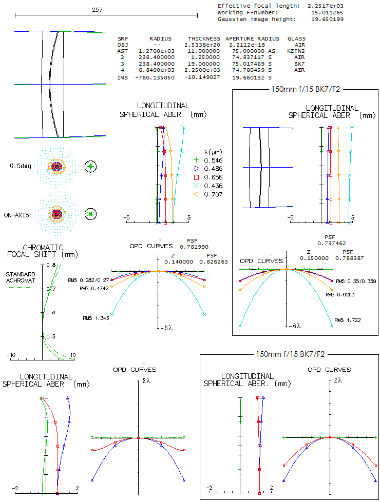
This rather a small aperture refractor for observatory setting
was not intended for professional-level use. It was designed by
Zeiss as an observatory/educational instrument for public use,
i.e. for popularization of astronomy. Its Coude-style mount
makes the final image stationary, independent of the movements
of optical tube. The mount is very massive, requiring a permanent,
observatory-like setup. Both axes are supplied by an electrical
motor, and the tube can also be moved manually.
The standard version uses Zeiss AS objective, doublet achromat
using Schott KzF2 "short-flint" as the front element and BK7.
It is in reverse to the standard achromat, having positive
element (crown) in front, and negative (flint) behind. There
is no gain in chromatic correction, but the reverse arrangement
- known as the Steinheil configuration - requires more
strongly curved lens surfaces, thus all else equal produces
more of higher-order spherical residual, as well as more
spherochromatism. There is no formal eplanation known to me
of why Zeiss
opted for the Steinheil arrangment for its AS-objective.
The KzF2 seems
to be beyond obsolete nowadays, with hard to find refractive
properties data, and was raplaced for raytracing purposes with
the Schott KzFN2, its more environmentaly friendly, now obsolete
near-equivalent.
While it is commonly cited that this objective
has significantly - three-fold, or so - reduced chromatism vs.
standard achromat, raytracing shows it is much more modest:
about 22% in the F and C lines (when nearly balanced defocus-wise),
and in the violet g line. Chromatic focal shift graph
shows about half as much of defocus between paraxial F and e
focus for the AS objective (and no significant difference vs.
achromat in the position of paraxial C-line focus), but that is not
relevant in the presence of significant spherochromatism. What
matters is where the best focus is, which is displaced from
paraxial focus due to spherical aberration, generaly stronger
in the reverse, Steinheil configuration. Note that this particular
objective has correction set for nearly balanced error in F and C;
the actual objective could have somewhat different correction mode,
closer to the one with the paraxial F and C foci coinciding
(i.e. favoring the red end).
Bottom graphs show
the imbalance in the F vs. C defocus error when their paraxial
foci coincide: it is significantly larger in the Steinheil
configuration, favoring the red line correction. When the
two lines are balanced, this AS objective has chromatic
correction at the level of the f/19.2 standard achromat.
The second flat can be rotated, allowing alternating between the lower
and upper focus position. According to
Zeiss,
standard accessories
include five eyepieces (one of them for Sun image projection),
one finder eyepiece, one reticle with illuminating device, one
pointing eyepiece, one neutral density glass filter, color
filters, one ring micrometer, eyepiece spectroscope, and two
2-fold eyepiece revolvers (one for stelar observtions, the other
with light-attenuating device for visual and photographic solar
observations). On request, the standard AS achromat can be
replaced by a 150mm f/15 or f/11 triplet apochromat (F-objective).
Introduced back in the 1960, this unusual telescope was the largest
reflecting telescope in Europe at the time, and still is the largest
Schmidt telescope in the world. It is the main telescope of the
Tautenburg Observatory near Jena, Germany. Beside Schmidt
configuration (f/3), it can also be used in Nasmyth (f/21) and Coude
(f/46) configurations, when the corrector is removed, and a
Cassegrain secondary placed at 3.44m from the primary. In the Schmidt
configuration, its aperture at the corrector is 1.34m, and in the other
two it uses the entire 2m mirror. The main 2m f/2 mirror is spherical, made
by Carl Zeiss company, originally from low-expansion ZK7 crown, in 1996 replaced
by identical mirror made from Sittal. No specifics seem to be
given on the size of
central obstruction (s), but the minimum dictated by a configuration
is 24% linearly in the Schmidt, and 14% in the other two configurations.
The actual obstruction is probably larger, particularly in the
configurations with secondary mirror, due to baffling requirements.
For that reason, central obstruction is omitted in raytracing; its
effect shouldn't significantly change the output.
In the Schmidt mode, it originally used 24cmx24cm photographic plates,
corresponding to 3.3°x3.3° angular field. Nowadays it uses
nearly 1° square CCD with up to 4096x4096 pixels. Either had
to be bent to match the best curved field of -4000mm radius. As
the astigmatic plot shows, field curvature induced defocus at 2.3°
off axis is 3.2mm, which translates to some 80 waves P-V of defocus
(2.3° field radius corresponds to the very corner of the photographic
plate, with the 0.7 field, or 1.6° is near the plate sides). Even
with the much smaller CCD detector, if flat, the curvature-induced
defocus would have been
3.9 waves P-V near the side, and twice as much in the corner. Over
the best field, the dominant off axis aberrations are oblique
spherical and astigmatism, creating a peculiar wavefront shape with
roughly flat outer area horizontally, while bent down vertically.
The resulting ray spot plot has a shape of wings oriented vertically.
Over the entire photographic plate field, correction is excellent;
in the very corner, it is still as low as 1/20 wave RMS in e-line,
well within the "diffraction-limited". Spherochromatism is relatively
low, the highest in the violet (still, the g-line error is at the
level of a 100mm f/65 achromat). Radius encircling 80% of the energy
is 0.0027mm on axis, and 0.003mm at 2.3° off. It translates to
a circle 0.28 and 0.31 arc seconds in diameter, respectively, for
photopic sensitivity (to illustrate correction level in the visual
domain), and 0.0043mm/0.0047mm for the average (roughly) CCD
sensitivity.
In either configuration with secondary mirror, the imperative is to
correct tons of spherical aberration induced by the 2m f/2
spherical mirror. Needed secondary deformation, as well as secondary's
radius of curvature for the Nasmyth focus are shown in the box
next to it. It requires 8.18 conic (oblate ellipsoid) for the
correction of primary spherical aberration (it could be also
expressed as a 4th order coefficient, but the conic is more telling),
and another three higher order terms, 6th, 8th and 10th, with the
yet higher order residual remaining at 0.067 wave RMS. Coma cannot
be corrected at the same time, limiting usable field size to a few
arc seconds. Although one source states that the usable field is
10-20 arcseconds, raytrace shows that already at 0.001 degree
field radius (0.75mm, or 3.6 arc seconds) coma is sufficiently large to mainly
desintegrate central diffraction maxima. This small fields are still
sufficient, since unlike the Schmidt camera, the long-focus configuration
are intended for studying individual, generally very small objects.
Both are used as spectrographs; the Nasmyth for faint stars and
galaxies (Nasmyth spectrograph is mounted on one of the two fork arms),
while the Echelle spectrograph at the Coude focus, with 30-100 times
higher resolution, is located in the basement of the dome building
(it is used for more detailed studies of relatively bright stars).
Angular field wise, correction is practically identical at the Coude
focus, only the image scale (i.e. linear field) is larger in proportion
to the f-ratio. The needed secondary conic is somewhat lower, 6.9733,
with somewhat different higher-order terms.
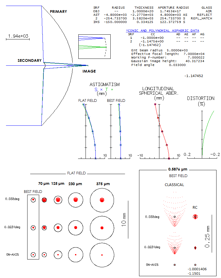
Back in 1984. Roderick Willstrop of the Cambridge University Observatory
came up with a design for large survey telescopes - a three-mirror
system similar in configuration to the Paul-Baker telescope. The
later has a great simplicity, using a paraboloid for the primary, and
two spherical smaller mirrors to achieve impecable correction over
wide field (the
flat-field variety uses ellipsoidal secondary).
However, large fast systems of this kind generate unacceptable level
of higher-order aberrations, setting the relative aperture limit at about
f/3 (it varies somewhat with the aperture size). Willstrop found
that higher-order aberrations can be greatly minimized, or completely
eliminated by putting appropriate higher-order aspherics on all three
mirrors. Since it was Bernhard Schmidt who first introduced this
type of surfaces, Willstrop presented his new design as Mersenne-Schmidt
(Mersenne telescope is a Cassegrain system using confocal secondary,
hence producing collimated beams). While it has its merits, the
system is still directly related to the
Paul-Baker telescope, and
hereafter will be referred to as Willstrop-Paul-Baker (WPB) telescope.
The
first system, 5m f/1.6 published in 1984., had a curved best field,
and the
second one, 5m f/2.6 published the following year, was flat-field.
In his papers, Willstrop gave a complete prescription for both
systems, but they are not usable with raytracing programs. The
reason is that Willstrop himself - according to Bob May's
page
(the other two related articles can be opened by replacing 3 in the
address bar by 2 and 4) -
didn't use raytracing software, and his prescriptions use forms
not compatible with raytracing software, possibly to some extent
even personal (for instance, he describes 2nd and 3rd mirror as
"approximately spherical", yet the sagitta given with the a2 term
implies paraboloid as the base shape for both; the 2nd mirror
radius - probably related to the sign of sagitta - is given as a
positive number, which in any Cassegrain
configuration implies concave, not convex surface, and alike).
In order to make prescriptions workable, it was necessary to
asign to the 2nd and 3rd mirror the base shape different than a
sphere (paraboloid and oblate ellipsoid with eccentricity 1
for the f/1.6 system, and paraboloid and a weaker oblete ellipsoid
for the f/2.6) and, of course, to asign to the 2nd mirror a
negative radius value. Even then, this was only taking care
of the 4th order aberrations; in order to minimize 6th and
higher order aberrations it was necessary to tweak the higher-order
coefficients. This means that the systems presented here are
different in prescription from the original, but they are within
Willstrop's main frame, and the correction
level is comparable.
The first system, f/1.6 with a curved best surface (top) has
a hole in the primary of nearly 60% the aperture diameter,
and it is assumed to be the effective central obstruction. Willstrop
gives two versions for the curved field configuration, for 2°
and 4° field diameter. Also, for the flat-field version gives
spots for 3° diameter, but in either case full illumination is provided
only for 2° field diameter. Only the 2° field version
will be considered here for the curved-field WPB, as well as
2° field size for the flat-field
arrangement (spot size increases significantly in the 4°
curved-field version, and beyond 1° field radius in the
flat-field arrangement).
To demonstrate the fine tuning system performance by balancing
the coefficients - i.e. the corresponding aberrations - the
first system is shown with a low residual astigmatism, corrected with
rather small changes in some of the coefficients (box below).
The second system, f/2.6 with flat best surface, has somewhat smalle
hole in the primary, determining the minimum central obstruction
to 50% of the aperture diameter. After the initial
correction of higher-order aberrations (mainly coma, corrected by
changing 4th order coefficient on the secondary for primary coma,
and 6th order coefficient for secondary coma, with the resulting
spherical aberration corrected by adjusting primary's conic and
6th order coefficient) had some low
residual coma left in, not visible in the ray spot plot (bottom), and was
corrected in a similar manner (box below). In effect, both systems can be
made to be better than "diffraction limited" over 2° field
diameter. In general, designs here are shown with minimized
spherical aberration on axis. It is not uncommon that allowing
for some spherical aberration results in a reduced off axis spots.
Box next to the spherical aberration plot shows that introducing a tiny
amount of spherical aberration in this case results in a small,
but noticeable reduction in the off-axis spot size.
To illustrate how much of improvement it represents vs.
Paul-Baker with paraboloidal primary and spherical secondary and tertiary,
the f/1.6 configuration would have practically zero 4th order
aberrations (except Petzval curvature and distortion, which are
the same as in the WPB), but its best focus secondary spherical would be as
much as 71 wave P-V, making its ray spot plot 1.2mm in diameter
(about half as much for the dense core). With spherical aberration made negligible
putting aspherics up to 10th order on the primary, remaining
secondary (mainly) coma would be 37 waves P-V (nearly 0.5mm )
at 1° off axis. Putting appropriate higher-order aspherics
on the secondary and tertiary significantly reduces blur size
(below, top), but the blur is still about 0.02mm, or 1/2 arc
second at 1° off axis. While it could be further reduced in
final optimization, for "diffraction limited" level - or better -
over the field, more higher-order aspherics, as well as conics on the
secondary and tertiary are needed.
In the standard Paul-Baker flat-field arrangement with the
same primary and obstruction size, secondary spherical (mainly) would
have been "only" 5.6 waves P-V, with secondary coma little over
5 waves P-V at 1° off axis (with secondary spherical corrected).
Limited aspherizing here is sufficient to achieve very good
correction (middle). However, such system would have been significantly
longer, and also slower, than the WPB. Viable alternative is to use
smaller secondary, which allows for a faster, much more compact configuration
with smaller central obstrution (bottom, minimum secondary size 30%,
primary hole 50%). Limited additional aspherization results in
a good overall correction, and full aspherization, as the one
used with the WPB, would further improve correction. As the
prescription shows, even if this system is formally flat-field, the
actual best field does have not negligible curvature, due to
the higher-order Petzval curvature. It can be compensated for by
making tertiary radius of curvature weaker - in this case -6960mm,
with the secondary-to-tertiary separation made equal to it -
which, with small adjustments in some coefficients, nearly
reproduces this output on flat field.
A note on the puzzling inconsistency between zero astigmatism showing
on the plot, and the apparent significant astigmatism in the diffraction
image for the top arrangement. Aberration coefficients also don't confirm
presence of astigmatism, yet it is showing nevertheless?! Also, the
wavefront maps (central obstruction omitted for clarity) show the
presence of a significant off-axis spherical aberration as well!? A look at the
coefficients given by Synopsys finds that most of the astigmatic-like
deformation comes from oblique spherical aberration, which is nearly twice stronger in tangential vs. sagittal
orientation (it is also "helped" by some coma and trefoil). By definition, oblique spherical is secondary
aberration identical
in form to primary spherical, but proportional to the square of field angle; SYNOPSYS - at least this
ancient version I'm using - seems
to be misbranding secondary astigmatism as "oblique spherical", while its "secondary astigmatism"
could be actually the lateral astigmatism form, also secondary aberration which changes with the 2nd power
of field angle and in-pupil height, and 4th power of field radius (unlike 2nd, 4th and 2nd power, respectively,
with secondary astigmatism). Zernike
coefficients do not include oblique
spherical term, since it is not needed, and point to astigmatism as the dominant
component of the wavefront error. It seems logical that OSLO uses the same secondary astigmatism form
(lateral astigmatism), and does not list the other secondary astigmatism form, which is listed as secondary
astigmatism by Mahajan.
Multiple Mirror Telescope, with a primary consisting of 6
hesagonal (honeycomb) mirrors, each 1.8m in diameter, was
completed in 1979. at the Whipple observatory on Mount Hopkins,
Arizona. In 1998. as new technologies made feasible production
of large lightweight mirrors, the primary was replaced with a
single 6.5-meter mirror of slightly larger outer diameter,
but with more than twice larger collection area. New telescope is a
versatile, multipurpose instrument with as many as three
interchangeable secondary mirrors, providing f/5, f/9 and
f/15 focal ratios in a classical Cassegrain design. The
widefield, f/5 mode has two configurations, one spectroscopic
and the other one imaging. Both use field correctors for
achieving wide, well corrected fields. The one presented here
is the MMT widefield imaging configuration, as described in a
paper by Fabricant, McLeod and West.
By design, field diameter of this version is 35 arc minutes,
or just under 0.6° in diameter. It is not particularly
wide angularly, but linearly it extends 0.365m in diameter.
While in the paper this arrangement goes as f/5 (which is a
focal ratio of the bare Cassegrain configuration), prescription
given there produces f/5.36 system. Ray spot plots presented
here are for the minimized axial spherical aberration - for
that purpose the secondary conic was slightly changed - although
the actually used imaging plane may be somewhat defocused. Field
corrector consists of three lenses, followed by field flattener
placed near image plane; in front of the flattener is a glass
filter. System is raytraced in the usual visual spectral range,
but telescope is used in a wider range, 330-1000nm. Size of
central obstruction wasn't specified; considering that the minimum
secondary size in this configuration is about 25% of the aperture
diameter, it is assumed to be 30%.
Design limit for the central line (here 546nm) exceeds 0.97 Strehl
in the field center. The corresponding ray spot plots for the
central wavelengths, as well as all five - shown next to the
field corrector - indicate excelent longitudinal color correction,
confirmed by the tightly woven together OPD plots (the 0.0072mm scale
represents the 0.546nm Airy disc diameter). Off axis ray spot
plots for angles larger than 0.1° become significantly larger
than Airy disc, with correspondingly bloated diffraction pattern.
Still, the plots, and the patterns' dense areas remain within
0.05mm, or 0.3 arc seconds circle (for clarity, diffraction
patterns are about 25% larger). According to the paper, 80%
encircled energy circle diameter averages out at 0.018mm, and
90% EE at 0.024mm - about 0.11 and 0.14 arc seconds, respectively,
roughly three times the Airy disc diameter (which is about three times
smaller than in the spectroscopic configuration).
In operation since 1977 at Las Campanas observatory in Chile, this telescope
was designed for direct astrophotography. It is a modified
Ritchey-Chretien (RC), which uses single aspheric plate as a field corrector
(Gascoigne corrector). Details, including prescription data, are
given by its designers (The optical design of the 40-in telescope
and of the Irenee DuPont telescope at Las Campanas observatory, Chile,
Bowen and Vaughan, 1973.). It is designed to cover field of 2.1°
in diameter. Correcting plate removes astigmatism, but induces
significant coma, which requires more strongly aspherized secondary
(to correct for coma) and primary (to correct for spherical aberration
induced by the stronger secondary) than in an all-reflecting RC. The
field is moderately curved (9m), requiring bending of the detector. Secondary
diameter is 95cm, and central obstruction somewhat larger (not
specified), taken to be 40% of the aperture diameter.
Raytrace below (top) shows low residual astigmatism, good color correction
and somewhat stronger best field curvature. Part of the difference
could be that the published ray spot plots show roughly even spot
size across the field, implying that the field was somewhat
defocused and/or shifted from the best image surface in order
to equilize the spot size. Diffraction images at 1° off -
monochromatic (left) and polychromatic (right, even sensitivity
for the five wavelength) - and on axis
(small box at right of the system drawing) show that the blur
at the field edge is smaller than 0.3 arc seconds, as was claimed.
For comparison, an RC telescope in this configuration but without corrector
would have as much as 59 waves P-V of astigmatism at 1° off
axis, on the best image surface, slightly over 1mm (nearly 11 arc
seconds) in diameter. Also, best image surface is nearly four
times more strongly curved.
Making corrector's 4th order coefficient slightly stronger,
reduces astigmatism to zero, producing better corrected outer
field (middle). Best image curvature is now 9m, with the
chromatic correction remaining, as expected, nearly unchanged
(vertical elongation in the diffraction image at 1° would have been
somewhat less pronounced with the actual, CCD sensitivity).
Encircled energy plots show better energy concentration for
the second system (in which the center field error was also
minimized), although the difference is relatively small. The
respective PSF, however, show what is evident on the diffraction
images, that the astigmatism-free version has smaller area of
energy concentration, translating to a higher detecting/resolving
potential.
Note that the two conic/aspheric data columns appear to
differ significantly,
but the actual difference is small. The original prescription
describes surfaces through the sagita (a2 coefficient times aperture
radius squared), adding to it the (conic) a4 coefficient (which
multiplies with a 4th power of the radius to produce surface sag
which in effect corrects value of the conic),
and a6 coefficient (multiplies with a 6th power of the
radius for the 6th order surface sag).
The a2 value in the original prescription defines a sag of paraboloidal
surface as the starting shape, with the a4 coefficient effectively
correcting the conic value, and the a6
coefficient addressing the 6th order surface/aberration domain
(for instance, taking a4 coefficient for the primary, it gives the
conic value from K1=8R3a4-1=-1.2, where -1 represents
the starting paraboloid; if starting shape is a sphere, the a4 value
simply needs to be six times larger to represent -1.2 conic).
The other prescription uses simpler notification,
defining starting surface shape as a sphere - raytracing default -
with a conic alone added (which puts
the value of the effective conic correction, a4 coefficient, at
zero), with the higher-order coefficients omitted as having relatively
small effect (they can clean up the vertical ray scatter, but
wouldn't appreciably reduce the RMS wavefront error, nor improve
diffraction image). The conic values (obtained from a2+a4 values
in the original prescription, and
as a conic alone in the
zero-astigmatism system) are very close.
A telescope with unusual destiny. It is the last observatory telescope
for which the optics was designed and superwised by D.D. Maksutov.
It is considered one of his best, if not the very best design.
In the early 1964. when the optics for AZT-16 ("AZT" stands for
"Astronomicheskiy Zerkalyniy Telescop", or "Astronomical Mirror
Telescope", and 16 is merely the number in a series of various
reflecting telescopes) was in its finishing stage, Maksutov
was at the institute around the clock, even slept there, to make
sure the optics will be completed (his health was poor, died in
August that year). In 1968. AZT-16 was installed at the peak of Cerro El
Roble mountain, Chile, to be active till 1973, when due to Pinochet
coming to power the Soviet astronomers were forced to leave,
with AZT-16 staying behind, conserved. After four decades, Pulkovo
observatory, who owns the astrograph, regained access to it. The
instrument has been found to be in serviceable condition, but needs
modernization/automatization. Chilean astronomers were taking care
of it, considering it to be a very special instrument; so much so,
that they've put a plate on it, reading: "Este es el Maksutov mas
lindo del mundo y sus alrededores" ("This is the best Maksutov on
Earth, and in the Solar system").
The AZT-16 uses double meniscus - a positive, and negative one -
instead of a single meniscus of the standard Maksutov, with a
singlet lens corrector (Piazzi-Smyth lens) nearly touching the
image plane. It allows
better overall correction, in particular flat field,
near negligible lateral color error and better central line correction.
The primary is a mild prolate ellipsoid (K=-0.1257), which does
allow for somewhat more relaxed meniscus radii (also, as the article
mentions, provides the convenience of two foci for testing purposes).
A single-mirror system with such field corrector can have either
astigmatism or lateral color corrected, but field curvature
remains unacceptably large (it requires negative field lens,
adding to field curvature of the base configuration), and the
overall correction level is somewhat lower.
Also, the field remains strongly curved. Maksutov's design
flattens the field and reduces all aberrations, with a
relatively low higher-order spherical aberration residual
remaining (it could be
cancelled by putting 6th order aspheric on one of the meniscus
surfaces, but wouldn't appreciably improve field performance).
Below is a
complete system drawing, showing placement of the front opening, front
and rear meniscus (1), 1-meter primary mirror (3) and field corrector (2) in
the optical tube assembly. The glass used for all three refracting
elements is LZOS K8 crown, a
Schott BK7 (used in the raytracing model) equivalent.
AZT-16 prescription
was published in an article by Maksutov and his associates
(Трудах 15-й Астроннмической конференции,
i.e. Proceedings of the 15th astrometric conference, 1960).
This prescription, however has an error, as raytrace below
shows: central correction is somewhat off and, more importantly,
colors are not as tightly bound together as they
should be (top, in a box). It is not known to me if correction has
been made in that, or some other publication. Nearly all of the longitudinal
chromatism is induced by the field corrector, i.e. the two menisci are nearly
optimally corrected. But taking the field corrector out increases spherical
aberration residual to nearly 0.11wave RMS, from 0.073 wave with corrector,
and the possible minimum of 0.064 wave (either with a slight adjustment an
a meniscus radius, or by increasing mirror conic to -0.152).
The only way to bring
colors together keeping the field corrector is
either to change radii on one of the meniscus correctors, or change
the thickness and radii of one of them. Since the latter
requires more extensive alterations (including making the field
lens a positive meniscus), in order to illustrate near peak
performance of the design, radii of the rear meniscus vere
changed in order to bring colors tightly together, with some
minor compensatory changes of some other parameters (including
minimizing error in the central line). Resulting system is
shown below the box. Field is taken to be 2.3° in diameter,
as given in the article, although fields in excess of 5°
were used. Central obstruction size wasn't specified, but from
above drawing it should be about 1/3 of the aperture. The stop
is not given in the prescription, but it is mentioned in the
text (460mm in front of the first surface); its effect is minor,
as article puts it, it somewhat reduces "tails" of the ray spot
plots off axis.
The field is very even correction-wise, with the central
diffraction maxima at 1.15° of axis showing only mild elongation
due to lateral color error (the five wavelengths, even sensitivity).
Encircled energy is even slightly tighter at the edge, than in the
center, with the 80% energy circle radius below 6 microns (about
one arc second; but resolving limit for contrasty details is,
with the central maxima intact, approximately the Airy disc
radius, i.e. 2 microns, or 0.2 arc seconds).
On axis, such system can be "diffraction limited". Best balance
between astigmatism, lateral color error and Petzval curvature (which represents
image curvature for zero astigmatism) is achieved by adjusting
the thicknes and rear radius value of the field lens.
The above AZT-16 drawing does not agree with the prescription:
front meniscus is noticeably thicker than the rear meniscus,
and using primary's diameter (1m)
as a measuring unit also implies that the primary is faster, with
the entire assembly shorter. There is no specifics on the source
or date of the drawing on the site, for which is not clear is it
related to the Pulkovo observatory. But since it appears to
be a legitimate technical drawing of what would be at least a version of
the instrument, it deserves consideration. Raytrace (below) shows
that the drawing implies an f/2.9 system, not quite as well
corrected as the f/3.25, but not significantly worse. The only
discrepancy is in the menisci-to-mirror separation, which is
about 2.4m according to the drawing, but has to be nearly 0.5m
wider in the raytracing model in order to fully correct for coma
(both, front and rear meniscus are thicker than in the article
prescription, with the radii adjusted to achieve best color and
central line correction).
Field lens is thicker, and it is assumed that the lens-to-image
separation is somewhat wider (as could be indicated by the drawing).
At the 2.8m separation, low residual coma is showing in the
diffraction image (monochromatic @546nm left, polychromatic
for the five wavelengths, even sensitivity, right) farther off axis. It does not appreciably
affect encircled energy, and can be cancelled by moving the
menisci 9cm farther out (diffraction images below at 1.15°).
There is no displaced stop, as it
doesn't seem to be present on the drawing; its effect is very
small, anyway. Whether the actual instrument is closer to the
first, prescription-based, or the second arrangement, it can
be made to be a highly-corrected, low-distorsion flat-field
astrograph. OPD curves imply nearly 20% larger chromatism
vs. f/3.25 system. Note that the P-V wavefront error on axis
(e-line) is numerically inflated due to the manner in which OSLO
calculates it in the presence of central obstruction; the
RMS error value implies that the actual error is at the level
of 1/3 wave P-V of primary spherical aberration. It corresponds
to the canonical balanced 6th/4th spherical aberration with the
marginal and paraxial foci of the LA graph coinciding. But the
actual minimum here is when the two foci are somewhat separated,
0.078 wave RMS (with, for instance, R4=-1152.5mm), probably due to the presence
of a not quite negligible 8th order spherical aberration. The overall
chromatism is lower to a similar degree.
The main advantage of double meniscus is that it makes possible
to flatten field with astigmatism kept negligible. A single-meniscus
system with a singlet field lens for lateral color correction
can achieve nearly as good correction,
but the negative field lens adds to the system's Petzval curvature,
leaving as the only option a flat astigmatic field with rather significant
magnitude of astigmatism (or aplanatic strongly curved image surface).
A f/3.25 system would have somewhat better correction, as shown
below (the mirror keeps the same conic, to make systems fully comparable).
The central line is well within "diffraction limited" on axis,
and even 1.25° off diffraction patternn is still fully
preserved. Most of the 0.3% distortion comes from the field lens.
It can be practically cancelled by reshaping the lens, but it would
induce other aberrations; however, it is likely that there is systemic solution
for yet lower distortion without compromising overall output
(the thicker meniscus is probably related to keeping lateral color
error low, while optimizing the field lens shape for minimum
distortion).
Sub-millimeter and millimeter (far-infrared, FIR) wave range is where most of
the progress in our knowledge and understanding of universe is to take place.
A space telescope that would span uniquely wide range of radio frequencies,
combined with exceptionally large aperture was concieved in the mid 1980-s, in
then USSR, and the project carried over to the Russian Federation, as Millimetron
space telescope (also known as Spektr-M), due to become operational by 2029.
Initially,
diameter of the antena was supposed to be 12m, but later on was reduced to 10m.
Its spectral range varies somewhat with the source, spanning approximately
0.05-10mm range. It will work as a single dish, and as a part of sub-millimeter
space-ground VLBI interferometer, making possible sub-microarcsecond resoultion.
It will be able of collecting new information on formation and evolution of planets,
stars and galaxies, including processes near the event horizons of black holes.
Among instruments that will be used with it are Mmtron Heterodyne Instrument for
Far-Infrared (MHIFI, 0.3-7mm), Short-wave Array Camera Spectrometer (SACS, 70/125/230/375
micron camera, 50-450 microns spectrometer) and Long-wave Array Camera Spectrometer (LACS,
0.4/0.7/1.2/2.3 mm camera, 0.3-3mm spectrometer). Camera covers 1.75'x3.5' field, spectrometer
significantly smaller, and it can be as small as 2x2 pixels with heterodyne receiver
(data from 2008 paper; actual fields may be somewhat different).
Optical system is classical Cassegrain, consisting from 10m f/0.24 paraboloidal primary
and a very small secondary (little over 5% by diameter effective area), for the final f/7 focal ratio (the actual system will employ
a diagonal placed behind the primary, but it doesn't affect optical output). Raytrace shows
the perfect-system output for the four SACS bands, where the off-axis aberrations are
most pronounced. The -150mm field curvature effect is insignificant even at the shortest wavelength.
As a curiosity, the system output at 0.588 micron (d-line), over best field surface (bottom
right).
Making it aplanatic significantly improves off axis performance, as the ray spot plots
show (surface conics given at the bottom), but the difference is
negligible with much longer wavelengths used by the radio-telescope.
Ritchey-Chretien (RC) two-mirror system had become the system of choice for large observatory
telescopes. However, its quality field is limited by astigmatism and field curvature,
and for that reason observatory telescopes of this type commonly use field corrector to
improve field quality when it is needed. For very wide fields, the system has to have
large relative aperture, which makes field correction more complex. A paper from Siberian
State Aerospace University describes such system, using a Wynne-type integrated field
corrector (OPTICAL SYSTEM RITCHEY-CHRETIEN AS PANORAMIC WIDEFIELD TELESCOPE, Veselkov,
Zemtsova, Shilova, 2014). Note that the glass in prescription is LZOS K8 crown, which
is practically equivalent to the Schott BK7.
Since the corrector is integrated into an optimized system, the mirror conics differ from
what they would be in a stand alone RC (-1.292 and -11, respectively). The 1-m primary mirror
has somewhat stronger, and the secondary somewhat weaker conic,
with the front surface of the corrector also being aspherized. Expectedly,
central obstruction is large, around 50% by diameter (assumed in raytracing; minimum secondary
size is 41.4%). Prescription
given in the paper has a typo, because the final back focus falls more than 4mm closer than
specified, and the blurs are larger than those presented. The simplest way to bring the
final focus to nearly coincide with the one given in the paper is to make either primary
slightly weaker, or secondary slightly stronger. The former gives a bit better result, so the
primary radius of curvature is changed from -3553.14mm given in the paper, to -3554.6mm (it
also brings the ray spot plots very close to those published). The primary focal length that
produces exactly the same back focal length is -3554.885, but it nearly doubles e-line error
in the center, and also slightly worsens it at the edge.
The 215mm field is flat and well corrected, with the only significant aberration remaining
being trefoil. Due to it, the 80% encircled energy diameter increases from 11 microns on
axis to 17 microns 1.5° off. Field edge polychromatic blur is within 0.025mm circle
(1.26 arc seconds),
and so is the bright part of the diffraction image. Since the bright core is still present,
the corresponding limiting field edge resolution is significantly below 1 arc second. For
comparison, the stand-alone RC would have as much as 76 waves P-V of astigmatism at
1.5° off, with ~0.6mm blur size (best image surface).
While the longitudinal color correction seems to be at or near optimum, with the colors
crossing at approximately 70% zone, and the OPD plot about as tight as it can be, a
better overall correction is with the crossing at nearly 90% zone. This is not usually
the case, and the main reason it is here seems to be the large central obstruction.
Despite the OPD for this crossing location appearing significantly more stretched out,
the corresponding RMS wavefront errors average favor it, producing 0.922 polychromatic
Strehl, vs. 0.890 with the 70% zone crossing (the five wavelengths, even sensitivity).
The OPD is misleading here, inflated, because it is constructed based on the way OSLO
calculates the P-V wavefront error in the presence of central obstruction, where it
is measured vs. wavefront center, which practically does not exist. What matters is
only the actual wavefront, and how it measures up against the scale.
Situated on Cerro Pachon, Chile, at an altitude of 2700m, Southern Astrophysical Research
(SOAR) telescope is said to be
designed to produce the sharpest images possible with a ground-based telescope. It uses
active optics on both, primary and secondary mirror, with the rotating flat tertiaty mirror having
tip-tilt correction. The mirrors are made of Corning Ultra Low Expansion (ULE) glass.
Under average seeing, it enables it to have image quality of ~0.5 arc
seeconds at 0.8 micron wvl, and the addition of Adaptive Optics Module (ground layer
addaptive optics) in 2013 took FWHM down to
0.25 arc seconds (for comparison, HST resolution is 0.05-0.1 arc seconds). It is a two-mirror
system with two Nasmyth foci
and three bent Cassegrain foci (which, unlike Nasmyth foci, are not positioned on the altitude axis);
prime focus is not accessible. Each Nasmyth focus has a cluster of three interchangeable
instruments, plus one instrument on each bent Cassegrain focus. Instruments operate in spectral
range from the atmospheric cutoff in the violet at ~0.32 micron, to the near-infrared.
Central obstruction is 23% linear, probably the smallest one
allowing for efficient baffling. Fully illuminated field with baffling on is 10 arc minutes, or
198mm in diameter.
As an optical system, SOAR 4.1m telescope is just another observatory Ritchey-Chretien. What
was puzzling to me was that nowhere in the description there was a mention of field corrector. Is
the field small enough not to need any? A closer look shows that this is not the case.
OSLO gives best field curvature radius of 959mm, concave toward diagonal. While the six instruments
with widest fields would have at least acceptable outer field quality over the 959mm radius best field
(bottom left), only two (5 and 6) would have it over flat field. Considering that Latter on,
I saw a passing remark of a new
CWFS Acquisition Camera (#6) having also field flattener replaced, which indicates that all of these
instruments have individually incoroprated field flatteners. Even if it has the smallest field of all
six instrument, its field edge error is 0.052 wave RMS for 550nm wavelength, more than 17nm surface
error of the primary (depending on the surface profile, it can be anything from twice as much to
1/4 of it in the wavefront). The entire field could be flattened
(and partly corrected for astigmatism) with a simple field flattener; a singlet would exhibit some
lateral color in the outer field, but a cemented doublet would perform satisfactorily (bottom right;
five wavelengths shown are g,F,e,C and r-line, from light blue to orange, respectively).
However, with as many as five different focus locations, there would have to be as many field flatteners,
one for each. It was probably better solution to couple up each instrument with its individually
taylored flattener.
As a side note, the dominant field aberration over best field is astigmatism, and over flat field
it is defocus. Ray spot plot for 0.075° field point over best field is nearly identical in size
and appearance to the ray spot plot for 0.024° flat field, yet their respective P-V and RMS
wavefront errors differ significantly. Another reminder that the ray spot plot size and appearance
is not tightly releated to the wavefront error.
This 22-inch Maksutov-Cassegrain was designed by John Gregory, who at the time worked as an optical
engeener for the Perkin-Elmer Corporation, where the optics was fabricated. It saw its first light in 1965,
and in 2022 was relocated to New Mexico, to a better location. The design is unusual, having two secondary
mirrors: one, small, permanenetly mounted onto the meniscus, providing an effective f/15 system with
visually accessible focus, and the other, large flip mirror providing f/3.7 system with focal plane in
front of the primary mirror for astrophotography. It is among the world largest Maksutov-type telescopes:
there are two 70cm systems (both build during the Soviet Union era, one the double meniscus system described
above (#21), and the other one is at the Georgian National Astrophysical Observatory near Abastumani), and several
50cm systems, most of them also from that era. However, it could be the largest one that can be used for
visual observations, since the double meniscus system is astrograph, and tube length of the other one
strongly suggests it is also a single mirror system. Oddly enough, there is almost no information on the
design and optical system of these large observatory Maksutov telescopes. The Stanford 22-inch is a partial
exception: there is no published prescription, and even the basic
information, like focal length of the primary, are missing, but based on the
optical scheme, a detailed article by
the long time curator of the observatory (A
short history of Stamford Observatory, Charles Scovill 1995),
and photograps of the actual instrument making
possible to approximate element separations, a system similar to the actual one can be reconstructed.
The overall dimensions imply quite a fast primary mirror, around f/2.5, which inevitably results in a
significant level of higher-order spherical aberration, which can't be affected if keeping surfaces spherical.
For that, a higher-order aspheric needs to be put on one of the surfaces and, as the article states,
in this case it was the secondary mirrors. In all-spherical arrangement, f/15 system requires somewhat
stronger meniscus radii for optimally balancing spherical aberrations, and consequently has a larger
residual axial error than the f/3.7 system (0.21 vs. 0.14 wave RMS). The latter could probably function
well enough w/o aspherization, with the error remaining nearly unchanged over 0.5° field radius,
(aspherization mainly improves inner field performance), but both possibilities will be addressed.
The field is practically flat with the f/3.7 system, due to the near-zero Petzval and astigmatism,
and is effectively flat with the f/15 system, due to the small angular field. Central obstruction is
assumed to be 12cm (0.215D) with small secondary, and 26cm (0.465D) with the large one; it shouldn't be far
from the actual values.
The question of meniscus shape seems to be answered with the requirement of corrected coma being imperative
for the photographic use. If the starting shape is the one optimal with the small secondary, the f/3.7
system can't be coma free with or without higher-order aspheric. The same applies to the f/15 system if
the starting meniscus shape is the one optimal for f/3.7 system (i.e. for having optimally balanced 4th and 6th
order spherical), but coma would in this case be acceptable, not affecting appreciably visual observation
(and for the small secondary it seem to be causing astigmatism, as shown little later). Thus,
starting with all-spherical f/3.7 system (below, top), it does have an overall acceptable correction for
photographic instrument, the only exception being lateral color error in the outer field. It doesn't affect
the encircled energy value, because a lot of energy is spread away from the central maxima (which is still
clearly defined, and smaller than that in a perfect aperture, as it is with spherical aberration), but it
would cause severe elongation of the star image. It can be corrected with a negative singlet placed close
to the focal plane, without inducing significant other aberrations, and it is probably what was done in
the actual instrument.
As mentioned, putting higher order aspheric on the secondary mainly benefits the inner field correction,
which may, and may not be significant, depending on target. The reason is that adding 6th order term
induces higher-order coma, which is different in form than its lower-order cousin, hence the two doesn't cancel out
completely. The higher 6th order term, the more of this residual. At the 6th order term value needed to
reduce 6th order spherical to zero, the field edge error woul have been more than twice larger than without it.
Best approach seems to be to do only a partial correction of the 6th order aberration, without
significantly worsening field edge correction (bottom). Optimizing such system would call for minor changes,
in this case reducing meniscus-to-primary separation by about four inches, requiring reduction of the conic
from 1.86 to 1.6 (conic can be approximated with a corresponding value of the 4th order coefficient, i.e.
4th order curve, according
to CC~8[AD]R3, which is nearly identical for all but very strongly curved surfaces; in the bottom
system above, the effect of 1.6 conic is practically identical to that of -7.4-12 4th order term).
Chromatic correction is significantly better across the field.
If, keeping the same meniscus, large secondary flips down exposing the small secondary, which only has conic
added to optimally re-balance 4th and 6th order spherical, correction is poor, at a level between 1/3 and 1/2
wave P-V of primary spherical aberration on axis (below). Adding higher-order aspherics to remove
higher-order spherical aberration results is still nearly flat field, with significant astigmatism toward the edge
(bottom right, boxed). Here, again, plausible option is a partial correction of 6th order spherical, and better
outer field correction.
A closer look at the two secondaries - specifically at their aspherization - shows that the large secondary
needed somewhat peculiar shape, due to its large size effectively making the deviation in the 4th and 6th
term very similar in magnitude. In fact, when
the coefficient value multiplies with d4, i.e. d6, respectively (d being the
surface radius) they give nearly identical edge deviation. Since the two are of opposite sign, this means
that no glass is to be taken off the edge. Unlike the conic curve (here parabola) vs. sphere, where deviation changes
smoothly, aspheric on the secondary deepens toward the edge forming a wrinkle to meet the sphere at the edge
(aspheric curves are greatly exaggerated, in order to show the profile
shape). Due to the two aspheric factors (8th order factor can be neglected in that respect) having nearly
identical maximum deviation, there is no difference
between the paraxial and best focus correction, since the quadratic terms in the two respective best focus
relations, x4-x2 and
x6-x2, cancel each other out for any zonal height, reducing to the paraxial focus relation
x4-x6. So, if the f/3.7 secondary had higher-order aspheric put on, it would have this type
of profile.
Unlike the large secondary, the small one has 4th vs. 6th order deviation closer to their usual relative magnitudes,
i.e. the 4th term deviation significantly larger. As a result, when aspherizing is done using direct terms
(i.e. x4
and x6, for correction at the paraxial focus), it requires aspherization that removes glass in even
progression toward the edge (top). For the best focus correction (x4-x2 and
x6-x2), just as in the case of parabolizing sphere, aspherization requires removal of
significantly less glass, with the process being inverse to that of parabolization (instead of flattening 0.71
zone with a concave surface, here the ~0.6 zone is left untouched, with the removal increasing toward center
and edge;
note that raytracing can just configure surface without changing position of its vertex, but with a real glass
surface aspheric profile needs to be shifted so that it is entirely within the glass).
Overall, putting a higher-order curve on the secondary is the easiest way to reduce the 6th order spherical
aberration residual, but it is limited by generating higher order coma. Putting higher-order aspheric on the primary
doesn't have that limitation, and putting it on the meniscus (as in Maksutov's "Astronomical Optics"), is still
better. Roughly, higher-order coma in a large, fast Maksutov system fully corrected for 6th order spherical
aberration is several times larger with the aspheric on the secondary vs. primary, and the later has it twice
larger vs. aspheric on the meniscus. In general, the latter two can have coma minimized by relatively small
changes in the miniscus-to-mirror separation, while it would be much more challenging with the aspheric on the
secondary. But that is a formal point of view; in practice, a complete correction of the higher-order
spherical aberration is usually not necessary, or may not even be desirable. Chances are, the unique 22-inch
Maksutov designed by John Gregory was fit to meet its tasks. Non-design factors, such is the inhomogeneous
meniscus glass, or turbulent air above observatory building didn't help, but that is different story.
POST SCRIPTUM: After finishing above analysis, I came to realize I forgot what was mentioned
earlier, about best focus change in presence of large central
obstruction, particularly with Maksutov systems with a relatively significant 6th order spherical aberration
residual. Best focus shifts away from the location w/o obstruction and, consequently, the LA graph for best
focus location is tilted to the left. So, leaving raytrace at the best focus w/o obstruction for illustration
of the effect, here's what the large secondary system (small secondary does not cause appreciable focus shift)
looks like for the system at its actual best focus.
Correction significantly improves across the field with all-spherical system (left), coming fairly close to
"diffraction limited" 0.80 Strehl on axis (that same RMS wavefront value would with primary aberrations produce
~0.78 Strehl, but balanced 6th/4th order spherical aberration, due to the high slope areas on its
wavefront, has less favorable phase, i.e. wave interference). Putting higher-order aspheric on the secondary
still improves inner field correction, but at a price of less well corrected outer field, due to the higher
order coma induced by the aspheric (right). The all-spherical system is, overall, probably better for imaging, which
would imply that the large secondary was probably left spherical. Note that in both cases meniscus radii are
slightly more relaxed, in order to optimize longitudinal color correction.
This is an example of a modern large Maksutov-Cassegrain. While APM mainly markets commercial telescopes, it
also does smaller observatory instruments. Prescription was posted online back in 2017. on multiple sites. At
that time, the telescope was in pre-production phase, with a prototype made. Mostly due to a massive mount,
the quoted price was quite high: $300,000. However, online search does not return any more recent information on
this telescope, hence it is unknown wheter or not there is such unit(s) in operation. Regardless, it is worth
a look, and can be also compared with its older cousin: the Stamford Maksutov-Cassegrain above.
At f/8.5, the system is somewhat faster than the usual Maksutov-Cassegrain, with still moderately large central
obstruction (D/3). The prescription does not mention aspherics, so the starting point is an
all-spherical system. With 0.91
axial Strehl in the optimized wavelength, and somewhat soft outer field correction, it is acceptable,
but leaves something to be desired (below, top). Correction can be improved by putting aspheric on any of
the four surfaces. One indication that it was done is the thinner than the standard D/10 meniscus; it does generate
less of lateral color error, but also adds to the spherical aberration residual. The former remains beneficial,
and the latter doesn't matter if spherical aberration is corrected using aspherics.
Trying with aspherized primary, or secondary, or meniscus, shows that the higher order coma - a consequence
of using 6th order
term to remove 6th order spherical aberration residual - is nearly optimally balanced with the 4th order
coma (necessary
to minimize the overall coma residual) with the aspheric on the secondary, but not when it is on the primary,
or meniscus. 6th order coma nearly doubles when aspheric is on the secondary vs. primary, and is nearly six
times higher vs. meniscus. Field correction remains nearly unchanged, since with given meniscus' radii
4th and 6th order coma are more
out of balance with aspheric on the primary, and still more with aspheric on the secondary (in other words,
less of 6th order coma is offset by more of 4th order coma). Since it is easy to manipulate 4th order coma by
balancing 4th order term with one of the meniscus' radii, it implies
that the likely aspherics were put on the secondary.
For full correction of higher order spherical aberration are needed 4th, 6th and 8th term. Keeping
the published radii, chromatic correction is slightly overcorrected in the blue/violet, but it is still
excellent. Off axis correction is better, due to the removal of spherical aberration, with the best image
surface having significantly stronger radius than the best astigmatic surface (generally, due to the
presence of other off axis aberrations).
However, despite the aberration coefficients for 4th and 6th order
coma being nearly balanced, the edge point wavefront still shows presence of deformation similar to unbalanced coma,
and the diffraction simulation confirms it. Taking a closer look of the OPD graph, the deviation is similar
to unbalanced coma (bottom left; for some reason, OSLO gives it uncorrected for tilt, so the dashed line approximates
reference line for wavefront deviation with tilt corrected). It is different from the shape of ballanced
6th/4th order
(bottom left corner, boxed). The culprit are other off axis aberrations, most likely astigmatism
(primary and secondary), tertiary coma and the
ever elusive oblique, or lateral spherical aberration (showed by Synopsys as roughly half the magnitude of
the 4th and 6th order coma combined), undoing the coma balance. The solution is obvious:
since the wavefront has nearly comatic shape, the two coma terms need to be rebalanced, effectively adding
more of coma needed to minimize the existing wavefront deviation. It is 4th order coma that can be manipulated,
and since it has the same sign as the existing wavefront deviation, it was lowered by lowering the 4th order
term, to effectively add 6th
order coma in the amount needed to minimize the deviation (4th and 6th order coma have a similar profile).
Disbalance it caused in the spherical aberration correction is compensated for by slightly changing the rear
meniscus radius.
Graph in the middle shows the corrected wavefront at 0.3°, along the axis of aberration
(coinciding with the vertical
cross section of the wavefront map). Field correction significantly improved, as can be seen on both,
the ray spot plot and diffraction simulation (with aspheric on the primary, off axis error would be
about two and a half times lower, due to the 6th order term on it inducing less of 6th order coma; with aspheric
on the meniscus the error would be still lower, however,
aspherizing primary or - more so - meniscus, is significantly more involved).
For optimized color correction, the two meniscus radii would have to be slightly stronger, which suggests
that this optimization step didn't take place in the actual design. Axial color correction is close
to the optimum, with the blue/violet end overcorrection nearly eliminated (it is easy to accomplish
with a slight change in the two radii). The overall correction is better than with the Stamford Maksutov,
but for a fair comparison they should be using primary mirror with identical f-ratio (f/3.1 APM vs.
f/2.5 Stamford), and a similar size secondary.
Designed for high-precision astrometry, this peculiar arrangement is derived from Korsh's TMA (Three-mirror
anastigmat, which are also aplanatic) analisys. RAFTER stands for "Ring Astrometric Field Telescope for
Exo-planets and Relativity", as described in a paper by Riva et al. (2022). As illustrated below, detector
area is a small fraction of the available image area. Purpose of the very narrow annular
field is to preserve near constant signal response for points separated by up to 2 degrees, as a condition
for astrometric precision down to a fraction of the diffraction image. Detector area is 3.4 arc minutes (14.4mm)
wide, i.e. 0.25 sq. degrees, containing 66 4000x4000 50mas-pixel detectors (mas=milliarcsecond, 1/1000 of arc
second, in this case implying 3.4-micron pixel). Very high pixel density - over six along the 586nm wavelength
Airy disc diameter - makes possible accurate reproduction of the diffraction image and its intensity profile.
Other than detection of Earth-sized and larger exoplanets, high astrometric accuracy is needed for observations
related to general relativity and cosmology, such as the dark matter halo around the Milky way, properties of
binary stars with a black hole and neutron star companion, galaxies, globular clusters etc.
As the ray spot plots show, correction across the entire illuminated field is well within "diffraction limited".
Astigmatism is near-minimum at the detector zone. Distortion is significant over 1-degree field angle,
but about 25 times smaller over the detector radial segment. Central
obstruction is not specified, but it is close to 60%. It is caused by secondary and tertiary mirror - the latter
being somewhat larger than the opening in the primary needed to accommodate the image-forming light beams - with the
flat merely obscuring the mid-field, and causing some vignetting between the 0% and 100% illuminated field areas.
In a paper by Ackermann et al. the authors propose a large, 4m aperture spectroscopic telescope for space objects
identification. It consists of a segmented spherical primary, and a 3-mirror near-focus corrector, either with
a single-mirror objective, or with a two-mirror objective. Both configuration use a narrow 0.1° field (diameter),
and require large central obstruction. While the RMS spot size for the latter is significantly larger than
with its all-reflecting
2-mirror alternatives (Ritchey-Chretien, Dall-Kirkham, Pressman-Camichel), the authors argue that its advantage are
easier to make and align spherical main mirrors, with the RMS spot size being of secondary importance.
Also, that the mirror corrector - The Improved Spherical Aberration Corrector (ISAC) - is simpler than in the
known systems suitable for this purpose. Mirror correctors are
relatively new approach in designing large observatory telescopes, and these two systems allow for taking a closer
look of their use.
Starting with a single-mirror objective, the 3-mirror corrector is at the primary's focus, with a large baffle (3)
positioned at some distance in front of it in order to protect the final image from unwanted light.
The field is astigmatic, with the best image field radius of -0.9m (concave toward mirror corrector). Designated
field is, however, what amounts to a best fit flat field, with somewhat defocused center but more even correction
level across the field, with the 80% encircled energy radius of 1/3 arc second. Note that the astigmatism graph
always originates from paraxial focus, hence the designated focus - at the zero on horizontal scale - is somewhat
closer to it than to the best focus (where the center field error is the lowest). Out of the three corrector mirrors
only one is aspherized, with higher-order aspheric (5), but its aspheric is quite strong: at the edge, it is over
2mm shallower than a
sphere of the same vertex radius. It is so strong that replacing it with spherical surface would cause final focus
to shift nearly 0.8m toward the last mirror surface. Central obstruction by the baffle in front of the corrector is
nearly 50% linearly.
With the two-mirror objective, central obstruction imposed by the secondary mirror is ~15% smaller (secondary itself
is little over 1.5mm, but the cell is at least 10% larger). Overall correction is noticeably better than with the
single-objective system, although the difference in 80% encircled energy radius is not as large as the difference
in ray spot plot size. Defocus to the best fit flat field is somewhat larger, resulting in the center field error
increasing from 0.031 to 0.146 wave RMS, but that is still considered acceptable. The only corrector mirror with
an aspheric, a higher-order profile (5), here is little over 1.5mm shallower than comparable sphere.
◄
14.2. ATM telescopes
▐
14.4. Commercial telescopes
► |