|
telescopeѲptics.net
▪
▪
▪
▪
▪▪▪▪
▪
▪
▪
▪
▪
▪
▪
▪
▪ CONTENTS
10.2.3.3.
MAKSUTOV-CASSEGRAIN TELESCOPE
• History
• Types: Gregory and Rumak
• Aspherising for a faster system
• Field illumination
• Meniscus effect
• Approximating meniscus radii
• Mangin MCT
• Veselkov MCT
Full-aperture meniscus corrector can be also used in various
arrangements, including two-mirror systems, as described in Maksutov's
extensive writings between 1941 and 1946. Nowadays, it is most
often used in the
Cassegrain configuration (FIG.
186), hence these systems are known as Maksutov-Cassegrain
telescopes (MCT). The benefit of such an arrangement is - similarly to that in
combination with the Schmidt corrector - greater flexibility in
correcting primary aberrations than in an all-reflecting system.
The usual meniscus orientation is concave to outside, when its coma is of opposite sign
to that of the primary. It also generates more of higher-order spherical,
but negligibly so unless the radii are strongly curved (in the Maksutov-Gregorian,
where the secondary contribution for both, spherical and coma, is of opposite sign,
both are a disadvantage, and it works better with the meniscus convex to outside;
still, even with f/3 primary, a 200mm aperture has unappealing 1/20 wave RMS design limit
for spherical aberration, and the reduction in it by aspherizing primary coming at a
price of added coma).
As it will be illustrated in this text, an MCT with separate secondary can be
made corrected for all aberrations (correcting field curvature requires
large secondary mirror) in an all-spherical arrangement. In addition,
corrector's chromatism can be made nearly non-existent.
However, in compact systems with fast
primary mirrors, the strongly curved surfaces of Maksutov corrector quickly
begin to generate higher-order spherical aberration, which changes in
proportion to the aperture and, approximately, with the fourth power of
primary's relative aperture. It can only be corrected by applying
aspheric surface term to either mirrors or the corrector - something too
complex to be viable for amateur telescopes. While it varies somewhat
with the specifics of corrector, acceptable optical quality in this
respect doesn't extend significantly beyond a 6" f/3 primary level.
Another option is to have the primary aspherised, which allows for
weaker corrector, with reduced higher-order spherical aberration.
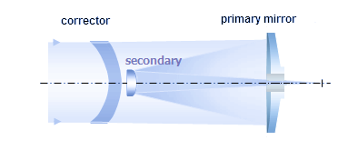
FIGURE 186: Maksutov-Cassegrain
telescope optical elements. Meniscus corrector, which induces not
only spherical, but also off-axis aberrations, offers greater
flexibility in correcting system aberrations. As a result,
Maksutov-Cassegrain can be made free from coma and astigmatism in a
compact all-spherical arrangement. The weak point is strong
higher-order spherical aberration with fast primary mirrors that
require strongly curved corrector surfaces. It can not be corrected
in an all-spherical arrangement. Secondary mirror can be either an
aluminized spot on the rear of corrector, or a separate surface,
which generally allows for better field quality.
First prototype of Maksutov's new telescope system was a
Gregorian
of 100mm aperture made according to his specs in 1941. With f/1.9 primary,
an all spherical design had about 0.4 wave P-V of balanced 6th/4th order
spherical (about 0.13 wave RMS) and worked
acceptably well only up to about 40x magnification. As an oddity,
it had focal plane
a few mm in front of the primary, only allowing use of longer focal
length eyepieces.
At about that time, being for a long time
deeply involved in making school telescopes, Maksutov initiated a
project of a small 70mm f/10 Cassegrain system serial production that will
resume in continuity after the WW2. Many thousands of this telescope
were made, known as Simplified School Telescope (УШТ
abrreviation for its name in Russian). There is no official prescrition,
but it can be re-engineered based on the specs from its brochure and
some published direct measurements, as shown below (note that it is the
optimized system; there are documents suggesting that the actual design
initially had sub-optimal color correction - according to the prescriptions
in Maksutov's papers,
nearly 1/2 wave in the red and over 0.6 waves in the blue; also,
actual measurements
suggest that manufacturing errors could have been significant).

It had a small aperture and field of view, but was highly portable
and went for what even in the Soviet Union was considered to be a low price (not
long after Maksutov's death, it was discontinued, which suggests that
it was his influence what kept such project going). The focal length
may have been longer than stated, and not strictly fixed. Early on, the eyepiece
was screwed on directly onto
the rear side, with a very short back focal length (later vesions had
it somewhat longer). The eyepiece was Huygenian
initially, and Kellner later on; it is possible that early on
some chromatism was left in intentionally, since Huygenian eyepiece has longitudinal
chromatism of opposite sign of that generated by the УШТ meniscus which,
as a few measurements suggest, tends to
have more relaxed radii than what is needed for a perfect chromatic correction. Measurement
of system parameters on an actual unit by Y. A. Klevtsov seem to support such conclusion. If that unit
is used with 14mm Huygenian eyepiece (for 50x magnification with the default f/10 system,
eyepiece prescription given in Maksutov's "Astronomical Optics"), longitudinal chromatism is practically
non-existent (below).

Spherical aberrations are less than perfectly balanced, but despite that the central line Strehl is nearly 0.97,
and polychromatic Strehl (photopic, 430-670nm) is over 0.94. A slight correction of ~0.04mm in the
radius value (stronger front, or weaker rear radius) minimizes spherical aberration and brings colors
optimally together, as in the fully optimized design above. However, the claimed field of 46' would
require more than 10 diopters edge accommodation (the corresponding distortionless field of view ~40°),
which leaves only about 0.7 of the field radius within eye's average accommodation range (note that the
field height value is for the objective's image; eye is replaced by OSLO "perfect lens" of 17mm focal length).
First published telescope arrangements in
the U.S. that followed the
1941 introduction of a full-aperture meniscus corrector for spherical
mirror was a pair of two-mirror Cassegrain systems - f/15 and f/23 - and
Maksutov-type corrector by John Gregory. In it, the secondary
was an aluminized spot at the back surface of the corrector. He published
two 6-inch aperture designs in a 1957 issue of Sky and Telescope, raytraced below (unit: inch).
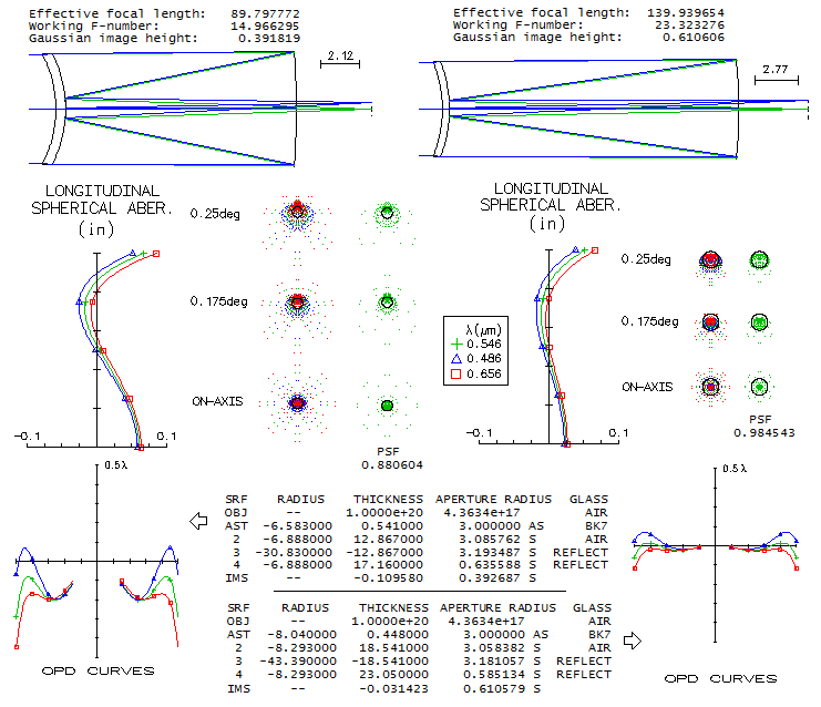
The f/15 design is pushing the limit of acceptable with its f/2.57
primary. The f/3.6 primary of the second design allows for the
correction level that makes possible fabrication of a "sensibly
perfect" telscope. However, both designes have longitudinal
chromatism corrected by bringing together paraxial foci, while
letting the more important, outer zones go to defocus.
Making meniscus radii slightly weaker - 6.78 and 7.095" in the f/15 system -
minimizes chromatic error, lowering it by about a half. But
even in the original system, the F and C error is well below quarter wave P-V level
if unoptimized, so it has relatively small effect. For today's standards,
both designs have too short back focal length, which means that both
would need to use a higher focal ratio (moving primary closer
to the corrector to accomplish that would have little effect and, if
needed, would be easy to offset by a very minor radius tweak).
Otherwise, designes are a fine example of creating Maksutov system,
which is not a simple task in any respect. Note that the spot
diameter is 1.4" in the f/15, and 1.2" in the f/23.
At the time, Lawrence Braymer was already producing his
famous-to-be Questar Maksutov-Cassegrain,
a design very similar to
Gregory's (in order to avoid patent infringement with a third party,
Questars had - for
about a decade - the aluminized spot placed at the front meniscus
surface). As a later development, an arrangement with separate secondary
was introduced.
Nowadays, both Gregory-type and the arrangement with
separated secondary are being used in various forms. In general,
separate secondary is preferred, since it gives additional degrees of
freedom for correction of
aberrations (FIG. 187).

FIGURE 187: Two basic
Maksutov-Cassegrain arrangements: (a) all-spherical with an
aluminized spot on the back of corrector for the secondary
(Gregory-style), and (b) with separated secondary. Due to
design limitations imposed by the two surfaces of identical radius
of curvature, the former has noticeably inferior off-axis
performance: at 0.4° off-axis the wavefront error (best surface) is
0.18 wave RMS, mostly due to the coma, but also astigmatism. The
design with separated secondary is highly corrected, with less than
0.06 wave RMS wavefront error at 0.7° off-axis (for identical
field radius, the maximum that can fit to 2-inch barrel eyepiece). It is also better
corrected axially (0.025 vs. 0.034 wave RMS), with lower field
curvature due to both, lower astigmatism and larger secondary.
Its minimum obstruction size is 0.30D, seemingly significantly larger
than in the aluminized spot arrangement, but due to the conical
baffle required by the latter, the actual difference is relatively small.
Some lateral color error (LC) exists, but not enough to be
intrusive visually. Both systems have very
low chromatism, with their photopic polychromatic Strehl practically
identical to the e-line Strehl.
Although known as all-spherical design, Maksutov-Cassegrain can also be made with
aspheric surfaces. While either of the two main types above can have aspherized surface(s),
in the amateur telescopes' arena it is usually the Gregory-style MCT, and it is usually the
primary that is aspherized. The reason can be either making possible more compact, somewhat
faster systems, or minimizing the higher-order spherical residual (or both, in larger apertures,
such as Astro-Physics 10" MCT). Meade had its well known 7" f/15 version, and nowadays they are fairly
common in the 4-8" aperture range, usually at about f/12.
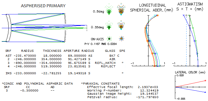
Aspherizing primary reduces the spherical aberration load on the meniscus, i.e. allows more relaxed
radii. Since aspherizing primary introduces positive coma, and a standard Gregory-Maksutov has
some residual negative (tail down) coma, this type of Gregory-Maksutov usually has residual positive
coma, with the degree of aspherization limited by the level of acceptable coma. System above,
with a -0.3 conic on the f/2.5 primary, has it at the visually negligible level (linear field like f/8.4 paraboloid).
Due to the more relaxed radii and shorter tube, lateral color error is also somewhat lower than in the
Gregory-Maksutov above, despite its slower primary. Balanced higher order spherical has 0.025 wave RMS
design limit (comparable to 1/12 wave P-V of primary spherical). The level of chromatic
correction is well illustrated by the violet g-line error: 0.032 wave RMS (0.96 Strehl). An f/15 system with f/2.8 primary, which
should be close to the Meade's 7" GMT in that respect, with the same -0.3 conic on the primary
would have less than 2/3 of the coma of this system (linear field), and an equivalent of
1/20 wave P-V of primary spherical aberration axial design limit. There would be no need for
significantly more aspherized primary, and it is all but certain that it is nowhere close to
parabolic, as some speculate, since such system can't be made
functional.
By manipulating corrector thickness with a conic on the primary, a compact,
relatively fast systems free of coma can be produced. Taking for example
the more common, smaller MCT, like Celestron 127mm f/12, here's what it would
look like with the standard corrector thickness (left) and thickness needed
to correct coma (right).
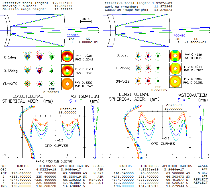
Due to the -0.33 primary conic making possible more relaxed radii, as fast as f/2.26 primary
can be used (can't be significantly slower for the f/12 final focal ratio).
Astigmatism is low (dashed on the astigmatism graph with 0.25D central obstruction
with the solid line representing the same system w/o obstruction;
actual obstruction is, due to the conical baffle around it, around 0.3D),
according to the graph 0.41 wave P-V at 0.5° off axis.
However, this strong conic turns the original negative (tip up) coma into
positive. It is still low, with the 5mm "difraction-limited" (0.80 Strehl)
field radius coresponding to f/7.8 paraboloid. E-line design limit is nearly
0.97 Strehl and, when the colors are optimally wrapped up, as shown, the
polychromatic (photopic) Strehl is practically identical to it. In order
to correct for coma, a lower primary conic is needed, and that requires
thicker meniscus, which generally requires weaker radii, hence lower conic
as well. The thickness needed to correct for coma here is about 20mm, with
the resulting system having a slightly worse e-line design limit (despite
somewhat weaker radii, due to its marginal ray at the primary being little
higher). But it has better field correction and a significantly more generous
back focal length.
One interesting aspect is the size of illuminated field. Taking the standard
thicknes meniscus, and 27mm rear baffle tube opening, assuming it is at 100mm
in front of the final image gives following result.
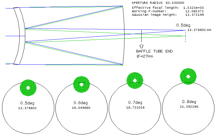 At 0.5° field radius, slightly smaller linearly than the baffle opening radius,
vignetting is already present, but entirely negligible. At 0.6°
it is still acceptable, but at 0.7° is barely passable (taking that
one magnitude illumination drop is the acceptable limit for field edge,
visually). That implies that the size of visually well illuminated field
is about 1/3 larger than the baffle tube opening. In this case, about 18mm,
or nearly 0.7 degrees true field (apparent field gets enlarged or reduced
according to the eyepiece distortion level). Note that this ignores vignetting
at the secondary and the baffle tube front opening; the former is generally
negligible, but the latter is likely to be significant
(see C9.25 baffling), although it is vignetting
at the rear baffle opening which ultimately determines the size of usable field.
This implies that this 5-inch Maksutov-Cassegrain does have illuminated field large
enough to use 2" eyepieces, although those with the widest field stops
will be severely vignetted close to field edge.
As described in the
previous section, full-aperture meniscus corrector has properties making
it quite complex optically. Part of it is due to its steeply curved
surfaces, generating significant amount of higher-order
aberrations. It is a thick lens, requiring more complex expressions for
accurate assessment. Also, its relatively strong power makes system
properties - including spherical aberration level - dependant on its
location relative to the mirror. In two-mirror systems, this only
becomes more complicated with the secondary mirror added. As a result,
the path to defining a working system of this kind is fairly
complicated, and can not be expressed with reasonably small set of
equations.
With the arrangement
with an aluminized spot for the secondary, needed secondary curvature
for desired focus location determines back radius of the corrector, thus
the only variable is corrector thickness and, to that extent, the front
radius. The secondary curvature itself is determined by the properties
of primary, which in turn are known only with the corrector properties
specified. However, there is a typical level of the effect of the
corrector on the primary, which can be used to obtain better initial
approximation of needed system properties (FIG.
188).
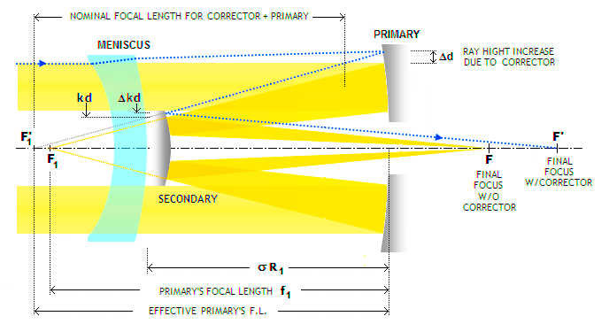
FIGURE 188:
Effect of placing full-aperture
meniscus corrector in a two-mirror system (dotted blue). Being thicker toward the
edges, meniscus delays outer portions of the flat incoming wavefront
more, changing its form into convex toward the primary. As a result,
the outer rays diverge, as if coming from an object placed at
meniscus' focal point (in terms of lens power, the meniscus is a
negative lens). Due to the aperture stop being displaced from the
primary, ray height at the primary is greater than at the first
corrector surface (aperture opening), making the primary's optical
radius
larger. It also focuses (F1')
farther away than without corrector in place (F1). Ray height on the
secondary also increases from kd (k being the height
in units of the aperture radius d) to (k+Δ)d.
Since the corrector causes primary mirror to form its image farther away from the secondary, it
re-images it at a greater distance from its surface, shifting the
final focus F' farther out. Changes in the
ray/wavefront geometry resulting from corrector's power change aberration contributions of the two
mirrors. Typical ray height increase on the primary due to
corrector's power is 4%-5%, and primary's effective
focal ratio
F is reduced by nearly 0.1 (which is reflected in the slightly
shorter nominal focal length for the corrector and primary combined). These quantities help in the initial
estimate of needed properties of the secondary and the corrector for
given primary mirror.
Meniscus corrector for
an MCT can be closely approximated based on
Eq. 128-128.1, for
a single mirror system, corrected for spherical aberration induced by
secondary mirror. The correction is determined by
Eq. 154, and implemented by substituting
[1/(1+s')1/3]R
for R in Eq. 126.
Since the relative (in units of spherical aberration on the primary)
level of spherical aberration on the secondary,
given by s' value, is typically around 1/3 (neglecting the minus
sign, which merely indicates aberration opposite in sign to that of the
primary), the front meniscus radius in an MCT is generally somewhat weaker than for
the meniscus that would correct the aberration of the primary alone; rear
radius is then calculated based on the front radius approximation, as
given with Eq. 128.1.
Adjustment to the corrector in order to minimize
chromatism and spherical aberration are generally as those described
under this last equation.
As an example, let's take a 150mm f/10 Maksutov with separated secondary,
15mm thick corrector and f/3
primary. This relatively fast system
requires larger secondary, so let it be 0.33 (marginal ray height of
the axial cone at the secondary, un units of aperture radius) needed
for 200mm back focal length. The relative
value of s is given by (d2/d1)4/ρ3,
where d1=1, d2 and ρ are the aperture radius (taken as unit), secondary's
axial cone radius and ρ=R2/R1, the secondary's radius of curvature
in units of the primary's, respectively. Since ρ=mk/(m-1), with k=d2/d1,
and m the secondary magnification, it comes to ρ=0.47R1, or
-423mm. That gives s'=0.114, or little less than 1/9 of the aberration
at the primary. However, this assumes object at infinity for both
mirrors. In order to calculate the actual s' it is necessary to adjust spherical
aberration at the secondary by entering the object distance factor, given
for spherical mirror by (1-2ψ)2, where ψ
is the reverse of object distance in units of the mirror focal length. We know
that the object distance (image by the primary) is -150mm here,
and the focal length is -211.5mm. This gives ψ=1.41, and the
correction factor for the secondary's spherical aberration of 3.3.
So the actual level of spherical aberration on the secondary
is as many times higher, or s'=0.38 relative to the primary.
With this, the effective mirror radius to correct is R1e=[1/(1+s')1/3]R1,
or 1.17R1. Using this value to obtain 0.9R" as the front meniscus
radius approximation given by Eq.126, gives for the front meniscus radius
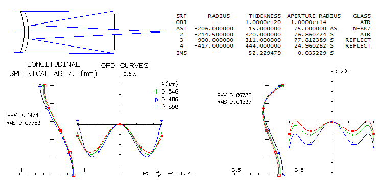
C1=-206mm. The corresponding rear radius (Eq.127) is C2=-214.5. Image below
shows this system before and after optimization. Considering that
calculation doesn't take into account higher-order spherical, it
is about as close as it gets.
In the Gregory-Maksutov, as mentioned, the additional
constraint is that the secondary radius coincides with the rear corrector
radius. For all spherical system, corrector radius needed to generate
spherical aberration that will - combined with that of the secondary -
cancel out spherical aberration of the primary is, in general, stronger
than the secondary radius required for usable systems with mid-to-low
secondary magnifications. When it is set equal, as in the Gregory-Maksutov,
it will produce diverging beam unless pulled farther from the primary.
Hence, secondary becomes both, more strogly curved and smaller. In
order to have both, corrected spherical aberration and accessible final focus,
Gregory-Maksutove typically requires secondary magnification larger than
5, most likely around 6 for the comfortable back focal length.
Usable systems with lower secondary magnification would require aspherized
primary, allowing for more relaxed corrector radii.
Because of the mentioned constraint, R2=C2, the latter being the rear
corrector radius, the above calculation for meniscus radius can't be
applied directly to Gregory-Maksutov: we don't know size of the secondary
before we know the rear meniscus radius, and can't determine the latter
without knowing the secondary size. The starting point is the
empirical approximate minimum secondary magnification value of 6. So
with the same f/3 primary the expected final f-ratio is around f/18.
From the back focal length, BFL=(m+1)k-1 in units of primary's focal
length, using m=6 determines value of k. In this case, BFL=200mm,
or 0.444f1, so k=1.444/7=0.206. The corresponding value for ρ
is ρ=mk/(m-1)=0.247, i.e. the secondary focal length f2=-222mm
(note that this is not also the
value for the rear meniscus radius yet, it is only needed for calculation;
rear meniscus radius has to be obtained from the spherical aberration
values). Now, with the relative spherical
aberration at the secondary s=k4/r3=0.12 for
object at infinity, and nearly twice bigger, or 0.233 when corrected
for object distance, giving R1e=1.092R1. With 1.17R1 producing -206mm, the front
meniscus radius here is C1=-192.3mm and the corresponding rear radius is
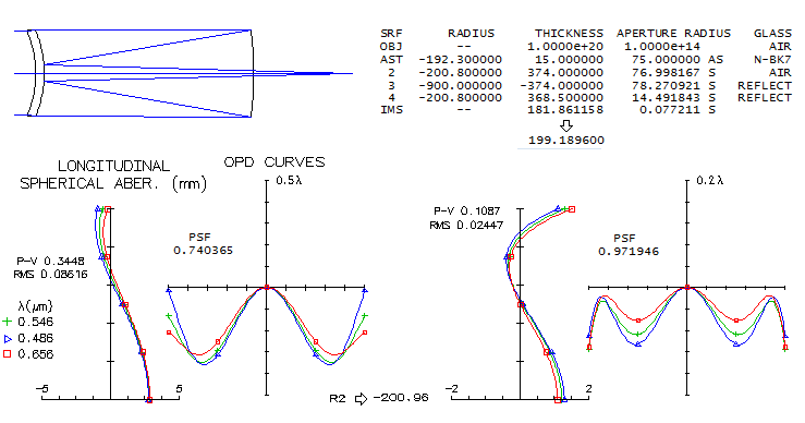
C2=-200.8mm. Raytrace below shows that these numbers are again spot
on chromatism-wise and quite close to the optimal values spherical
aberration wise. Note that after adjusting C2 value the back focal
length changes to 199.2mm, for the final f/19.5 system, i.e.
6.5 secondary magnification.
For a faster, more compact design, primary needs to be aspherized.
Following the same path with f/2.6 primary - which with K=-0.2 conic
(approx. the value cancelling out coma) has spherical aberration
of f/2.8 - and 200mm BFL, we approximate k
from BFL taking only fractionally smaller secondary magnification,
say, 6 (most of the system f-ratio reduction comes from the faster
primary). That gives BFL=0.51f1 (with the geometric f/2.6 primary),
k=1.51/7=0.216, and
ρ=0.26 (f2=-101mm), with the infinity s=0.124, and the actual s'
nearly two times larger, or 0.24. That gives R1e=1.1R1, with the front
meniscus radius approximated as 0.9R"=0.223R1.
What still needs to be accounted for is the effect of conic, which
lowers spherical aberration at the primary by 20% and, with
spherical aberration changing inversely to the 3rd power of radius
value, makes it effectively 0.9R"=0.24R1, or C1=-187.4mm. This determines
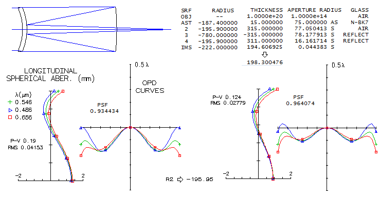
the rear radius C2=-195.9mm. Raytrace below shows another system close
to the optimum level, slightly closer in monochromatic correction,
and slightly less so in the chromatic (radii need to be about
5mm weaker in order to optimally wrap up the colors). The final
system f-ratio is f/15.8.
Two-mirror
Maksutov system aberrations are addressed in more details in the
following chapter. While fourth-order coefficients - in particular
for spherical aberration - are not sufficiently accurate for determining
final system properties, they are necessary for understanding
system's properties.
MANGIN-MAKSUTOV-CASSEGRAIN
An interesting possibility is to have a Mangin mirror for the primary,
i.e. to make it a positive meniscus with refraction at the front surface
and a single reflection at the rear surface. The same can be done
with the secondary by putting reflecting spot on the front meniscus side;
the effect of the latter is near-negligible, but turning the primary
into Mangin mirror allows for much more flexibility with respect to
the meniscus radii, making possible a significant reduction in the
higher-order spherical residual and faster systems for a given power
of the reflective side of the primary. In other words, produces
effects similar to those of aspherizing the primary.
As an example, image below shows a small 80mm aperture system
with the reflective side of the primary corresponding to f/2.5
mirror. Size of central obstruction is approximated by the diameter
of the secondary baffle opening, in this case taken as 28mm (35%).
Back focal length is on the short side, but acceptable for this small
system.
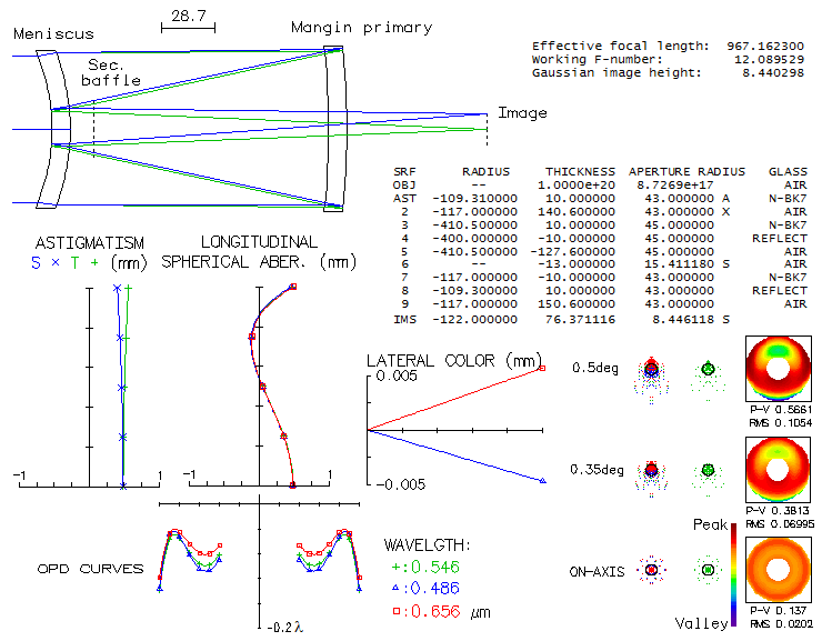
Overall, the output is quite similar to that of the standard
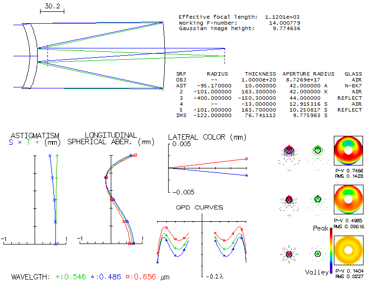
MCT. In order to pinpoint the differences, a standard MCT with
identical aperture and reflective surface radius of the primary
is shown below. For similar back focal length, it is slower at f/14
vs. f/12.1 for the Mangin arrangement. It also requires somewhat
smaller central obstruction, 23 vs. 28mm. Aberrations wise, the
reflective side of Mangin mirror and its front side (mostly second
refraction) induce roughly as much of spherical aberration and coma
as the primary mirror in the standard MCT. Astigmatism in the Mangin
arrangement is over 30% lower,
but lateral color error is three times larger (lateral color coud be easily
managed with a field lens, but that is an extra element which would
make comparison less direct). Meniscus radii in the standard arrangement
are somewhat stronger,
resulting in a little more of the higher-order spherical residual
(radii strengthening is necessary in order to bring the colors tightly
together; if only spherical aberration would be minimized by making
the front radius somewhat weaker, the defocus error for given
meniscus thickness would have been
about 1/2 wave in the red C line, and about 3/4 wave in the blue F line).
 . .
But, as mentioned before, the Mangin MCT can have its meniscus radii
significantly more relaxed, reducing the higher-order spherical
residual, with the chromatic defocus induced compensated by a change
in the front, refractive radius of Mangin mirror. Below is an example
of the initial Mangin MCT with significantly more relaxed meniscus
radii.
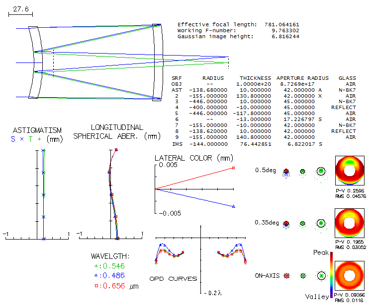
The system becomes more compact, faster (f/9.8), with the correction
error in the optimized wavelength nearly cut in half, with even less astigmatism
and 22% lower lateral color error (still more than double the error
in the standard MCT), but the price to pay is the larger central obstruction -
nearly 32mm (40%). Field curvature is more relaxed at -144mm radius,
vs. -99mm in the standard MCT (-122mm in the prescription is an oversight).
Overall, while using Mangin primary is a
viable option, aspherizing the primary achieves similar benefits
in making a system more compact and faster in a generally simpler way,
without negatively affecting lateral color error. It is also
less expensive vs. having another piece of high-quality optical
glass and an extra spherical surface to make. That is why it is
the preffered choice for manufacturers.
VESELKOV-MAKSUTOV TELESCOPE
In general, a compact MCT telescope has three residual aberrations, that
can be significant: astigmatism, coma and field curvature.
Astigmatism is generally low, coma varies with the system, i.e.
contributions of the meniscus and secondary vs. opposite in
sign primary contribution, and field curvature is inconsequential
visually, but not in imaging. While coma-free MCT systems are
possible, they require small secondary. The idea of MCT modification
by Veselkov (RU 2,449,329 Veselkov S.A. 2012) was to make possible
coma-free compact MCT with nearly flat field for faster systems
as well. To accomplish this, it was needed to aspherize secondary,
which removes coma, and set the radii of primary and secondary mirror
equal, in order to make Petzval curvature zero. Remaining mild field
curvature is a result of system astigmatism. Minimum secondary diameter
is just over 92mm, but the central obstruction would have to be
at least 100mm, or 50% linearly.
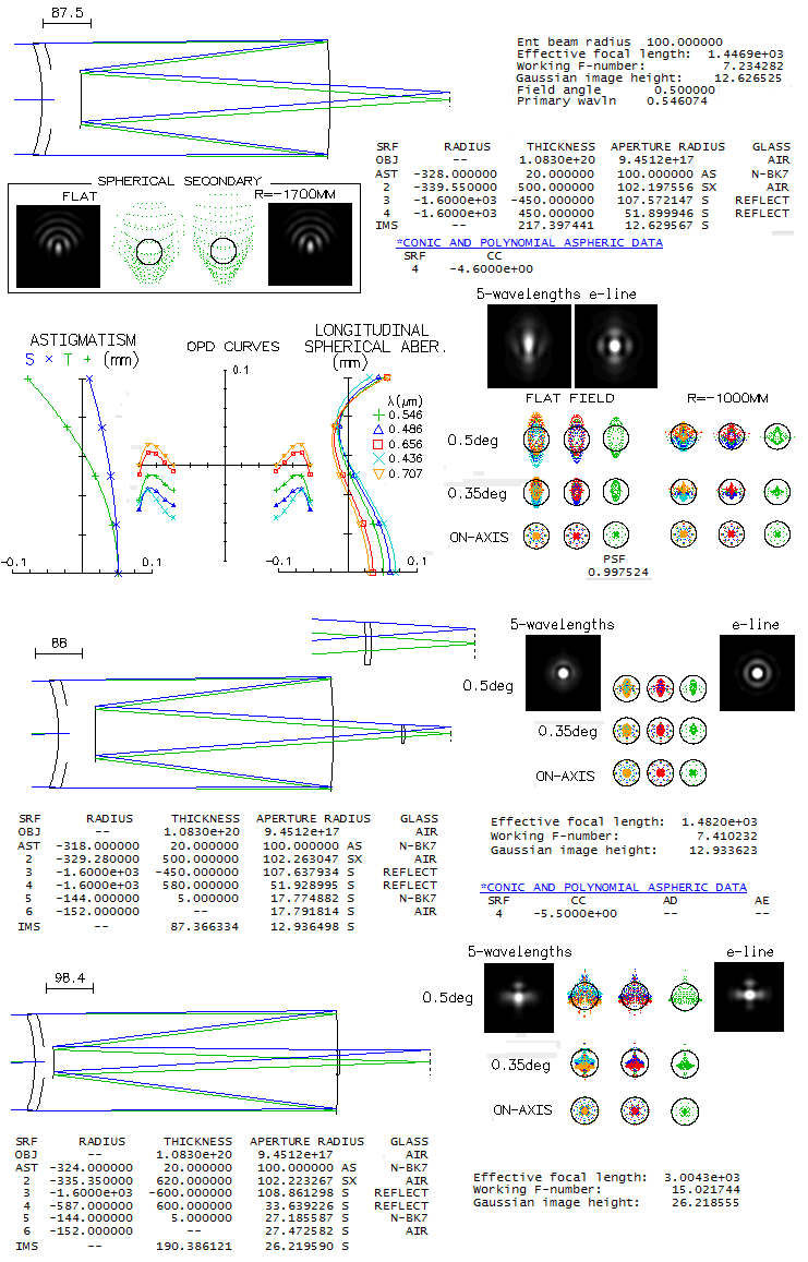
Top system is a Veselkov-type MCT. The original system described
in the patent application is a 200mm f/8,
but the main characteristics remain nearly unchanged with this,
somewhat faster system: mild field curvature
caused by the system astigmatism, and coma-free field (box below the
system drawing shows 0.5° spots and diffraction images for the
same system with spherical secondary). The secondary conic is
interchangeable with the meniscus distance: the closer meniscus,
the higher conic. The requirement
of equal mirrors' curvature radii inevitably sets the secondary large,
in order to have accessible final image. At 0.5° off axis, there
is barely detectable deformation of the central maxima due to field
curvature, but the elongation due to lateral color error (even
sensitivity) is readily noticeable. Field can't be made truly flat,
since nearly all of the astigmatism comes from the primary. Compensating
for astigmatism by non-zero Petzval would require significantly
weaker, i.e. larger secondary. Considering that 1-degree field in
diameter is well corrected overall, it wouldn't be justified.
For larger fields, both field curvature and lateral color can be
corrected with a single meniscus field corrector (middle).
Required conic on the secondary diminishes with the secondary
size; with the minimum size below 60mm (diameter), a coma-free
flat-field all-spherical system is possible (bottom). Note that the field
meniscus still has identical parameters, with the blue/violet
slightly undercorrected laterally, but it does not have noticeable
effect on the diffraction image.
◄
10.2.3.2. Maksutov-Newtonian
▐
10.2.3.4. Maksutov-Cassegrain aberrations
►
Home
| Comments |