|
telescopeѲptics.net
▪
▪
▪
▪
▪▪▪▪
▪
▪
▪
▪
▪
▪
▪
▪
▪ CONTENTS
◄
8.2. Two-mirror
telescopes
▐
8.2.2/3. Classical and aplanatic
► 8.2.1. Two-mirror telescope aberrations
PAGE HIGHLIGHTS The basic concept used for more detailed presentation of two-mirror aberrations is that given in "Astronomical Optics" from Daniel J. Schroeder. It requires only two parameters for computing system aberrations: one is secondary magnification m and the other, alternatively, either relative back focal distance η, or the height of marginal ray at the secondary (i.e. minimum relative secondary size) k (FIG. 122). The former is defined as the primary-to-final focus separation in units of the primary focal length, or η=B/f1=(m+1)k-1, where B, f1 and m are the back focal length in units of the primary mirror's focal length, primary's focal length and secondary's magnification, respectively, and the latter by k=1-s/f1., with s being the primary-to-secondary separation (both f1 and s numerically negative according to the sign convention). Use of parameters in their relative ("dimensionless") form generally simplifies the relations, also making calculation quicker and more convenient by leaving out large numbers (focal length, radii, etc.).
According to the sign convention, secondary magnification m is positive for the Cassegrain, and negative for the Gregorian, while the relative back focal distance η is positive for the final focus to the right from the primary mirror, and negative for the final focus to the left.
Following table details two-mirror system
parameters determining its geometric and optical properties.
Note that k and ρ are also positive for the Cassegrain and negative for the Gregorian. With the Cassegrain, the secondary will form real image with ρ>k; for ρ=k, the secondary will produce collimated beams, and for ρ<k reflected beams will be diverging (i.e. magnification is numerically negative). Likewise, with the Gregorian, the condition for the secondary to form real image is |k|>|ρ|, with positive magnification values indicating secondary too weak to form a real image.
Two-mirror system parameters , with respect to their sign, are
summarized in the following table.
TABLE 9: Numerical sign for main parameters of the Cassegrain and Gregorian two-mirror systems. General aberration coefficients for the two-mirror telescope are obtained as a sum of aberration coefficients for the primary (with the stop at the surface) and secondary mirror (with the stop at the primary). For cancelled lower-order spherical aberration in a two-mirror system, for object at infinity, primary and secondary mirror conics - K1 and K2, respectively - have to relate as:
This relation is derived by setting a sum of the spherical aberration coefficients for the primary (Eq. 9.2) and secondary mirror (Eq. 9), equal to zero. The sum itself, from Eq. 7, determines expression for the system P-V wavefront error of spherical aberration at the best focus for two-mirror systems in general as:
With values for K1 and K2 satisfying Eq. 80, the result is zero value for Ws. In Eq. 81, the (K1+1) factor inside the main brackets is the aberration contribution of the primary, while the complex right-hand factor is the aberration contribution of the secondary. Deviations from values needed for a zero-sum in the four contributing elements shown in bottom relation - mirror conics, secondary location and radius of curvature - can either add up or partly offset one another. For instance, it is evident that change in the minimum relative secondary size k (i.e. change in its separation from the primary) will be mainly offset by a similar relative change in ρ (i.e. the secondary radius of curvature). But that will change secondary magnification. Off-axis aberrations in two-mirror systems are coma, astigmatism and field curvature (distortion is usually negligible). General two-mirror system aberration coefficient for lower-order coma is a sum of the aberration contributions of the primary (Eq. 15.1) and secondary mirror (Eq. 15.2). After substitutions for the secondary's conic, stop (i.e. the primary) separation σ (FIG. 76, bottom) and the object (i.e. primary's image) distance factor Ω, in terms of the selected dimensionless parameters it can be written as:
Similarly, the two-mirror system aberration coefficient for lower-order astigmatism is:
with f being the system focal length. The P-V wavefront error at the best focus is, from Eq. 12 and Eq. 18, given by Wc=csαD3/12 and Wa=as(αD)2/4, respectively, with α being the field angle in radians. Good approximation for the level of coma in a two-mirror system from Eq. 82 gives system coma approximately changing in proportion to [2+(K1+1)m3/(1+η)]/2F12, F1 being the primary mirror focal number F=f1/D. For K1=-1 (paraboloidal primary), the coma changes as 1/F12, inversely to the square of the primary mirror F-number. For an aplanatic (coma-free) two-mirror system, needed primary mirror conic is approximated by K1~-1-2(1+η)/m3 (of course, coma of the primary is conic-independent as long as the stop is at its surface; the indication is indirect, due to primary's conic actually compensating for spherical aberration induced by aspherizing the secondary as needed to offset primary's coma). Two-mirror system Petzval and best (median) image field curvature are:
respectively, with the system focal length f being, as mentioned in the beginning, numerically positive for the Cassegrain and negative for Gregorian. For K1~-1, good approximation of the median field curvature, for η set to zero in the denominator, is given by:
The sign of Rm is negative for the Cassegrain, and positive for the Gregorian, indicating that median field curvature is concave toward secondary for the former, and convex for the latter. Graph below shows Petzval and median field curvature for classical Cassegrain and Gregorian (K1=-1), for back focal length η=0.25 (note that the system focal length is positive for the Cassegrain and negative for the Gregorian, thus the sign of field curvature is as appears for the former, but opposite to it for the latter).
On the other hand, Gregorian can't have flat Petzval (obviously, since employing two concave mirrors), but can have flat best astigmatic surface, for m~-1.6. However, such system is not practical, since the corresponding secondary is, from k=(1+η)/(m+1)=-2.083, more than twice the diameter of the primary. Practical Gregorian systems have m<-3.5, i.e. secondary's minimum size not larger than about 50% of the primary. For the same criterion, the lower magnification limit for the Cassegrain is m~1.5. Thus, while for given system f-ratio the Gregorian will have flatter best image surface (and larger secondary) - its median curvature is nearly identical to the Petzval of the Cassegrain, and its Petzval is fairly similar to the Cassegrain's median curvature - for given primary's f-ratio it is the Cassegrain that can reach faster system f-ratio and have a flatter best image surface not only in terms of the system focal length, but in absolute terms as well. For instance, with an f/3 primary the fastest that the Gregorian can go with the minimum 50% linear obstruction is ~f/11, vs. ~f/4.7 for the Cassegrain; the former has the best image surface radius ~0.15f, and the latter ~0.45f, or nearly 30% weaker. Variations in the back focal length from 0.25 are relatively small for practical systems (even in the Nasmyth arrangement and η~0 there is no significant change in the median field curvature), which means that these plots are representative of the two systems in general.
Incident ray angle and
the final image
Incident ray angle at any off-axis point
in the final image of a two-mirror telescope is significantly larger
than the corresponding incident angle at the aperture (primary mirror).
This is a consequence of the ray reflected from the secondary appearing
as if coming from the center of the exit pupil - image of the primary -
projected by the secondary. Larger image forming angles are not an
aberration factor in the final image itself, but are an aberration
factor for the eyepiece,
or other optical element following the image. Given system focal
ratio, eyepiece field aberrations in a two-mirror
system are larger than
in a Newtonian, or a refractor.
Secondary mirror in a two-mirror system
forms the system exit pupil (i.e.
virtual image of the primary mirror) in front of the
primary, at a distance E=-(1-k)ρ/(1-k+ρ)
from the secondary, in units of the primary's focal length, with k
being the height of marginal ray at the secondary (i.e. minimum
secondary size) in units of the aperture radius, and ρ the
secondary radius of curvature in units of the primary's (the negative
value of E inicating it is at left from the secondary, for the primary oriented
to the left). Since the chief ray appears as if coming from the center of the exit pupil, the incident angle at the off-axis image point is given by h/(E-s), h being its linear height in the image plane and s the secondary-to-final-focus separation (positive in sign). At the same time, incident angle at the aperture is defined by h/f, with f=-mf1 being the system focal length and f1 the primary f.l. Consequently, magnification factor of the incident angle at the final image is given by -f/(E-s), with the minus sign to make it positive. If expressing all in units of primary's focal length, it is m/(E+s), m being the secondary magnification (since the primary f.l. is negative, E turns positive, and since s is positive too, sign in the brackets is a plus). Thus, for average values of k~0.25 and m~4, the effective incident ray angle at the final image is over 3 times larger than the actual incident angle at the primary. It is greater for the Gregorian, since both, secondary magnification m and relative size k are numerically negative. Effect of the baffle system on off axis imaging
One of the consequences of the above mentioned angle magnification
by the secondary is more pronounced vignetting of off axis cones by
the baffle tube. By obstructing the off axis converging cones,
baffles in a two-mirror
system are effectively reshaping the aperture for the corresponding
image points. While it is not a wavefront aberration, it does
affect diffraction image of these points and, in presence of
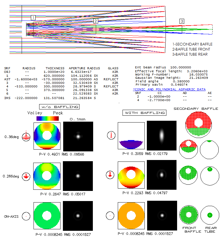
aberrations, it alters their appearance. Below is shown a classical
Cassegrain system with off axis light not affected by any obstruction
(left) and altered by the baffling (right). Field angle is chosen
so that it reaches field height near the 2-inch barrel limit,
specifically 21mm. Central obstruction is 34% linearly. As the
ray spot plots show, the off-axis aberration level is low, not much
over "diffraction limited" at 21mm off.
As the off axis angle increases, converging cone is increasingly
obstructed by the baffle system, primarily the baffle tube.
Consequently, area of the wavefront reaching image points is
more and more reduced, affecting appearance of the diffraction image.
The ray spot plot is also affected. Obstruction by the secondary
baffle is near negligible, even for the field edge (the red area
represents rays that will be obstructed later, by the baffle tube).
Obstruction of off-axis cone is significant at the front baffle tube
opening, but for the outer field (from about 3/4 field radius) it is
the rear baffle tube opening that does most of the obstruction, and
ultimately limits the illuminated field size. At the full field angle,
the effective aperture, indicated by the shape of the wavefront,
is significantly reduced in size and elongated horizontally. As a
result, diffraction maxima is correspondingly larger, and elongated
vertically (since the level of aberration is low, the deformation
is very similar to that in aberration-free aperture).
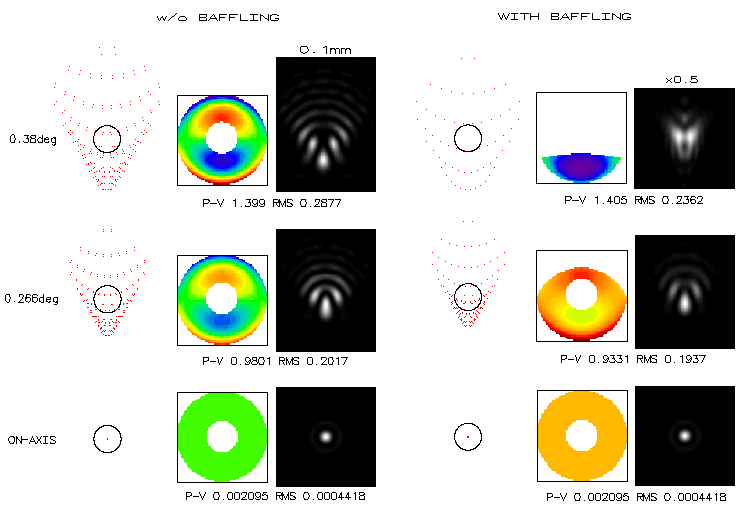
Turning the same system into Dall-Kirkham illustartes the effect
of baffle obstruction on aberrations of larger magnitude, in this case
coma.
At least roughly, baffle obstruction again begins to significantly
alter diffraction image at the 3/4 field radius, with the field edge
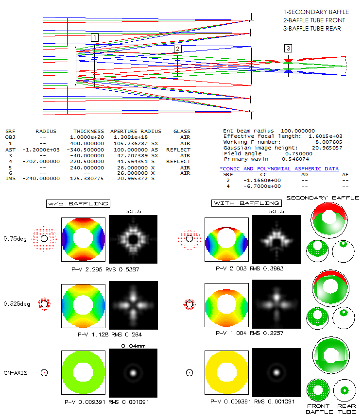
image enlarged, and not resembling coma anymore. Finally, taking
a 200mm f/3/8 Ritchey-Chretien, shows the effect of baffle obstruction
on its astigmatic off-axis image. The main difference is baffle
tube width, which is significantly larger than in the previous two
systems (48mm vs. 34mm, here identical to the central obstruction).
With the same size field, baffle obstruction is significantly smaller.
However, the symmetry of astigmatic image is disturbed already at the
0.7 field radius. In general, image side corresponding to the unobstructed
side of the wavefront fades away and ultimately vanishes. And unlike
the previous systems, most of the obstruction takes place at the
front baffle tube opening, with none at the rear opening.
Standard Schmidt-Cassegrain have the
relative baffle tube opening smaller than the Ritchey-Chretien, but
larger than the Cassegrain. Hence, there is some deformation in the
periferal field but not significant at the field radius considered
here (it is significant toward edge of the field that fits into 2-inch
barrel). Standard Maksutov-Cassegrain,
however, even with aspherized,
relatively fast primary, is closer to the Cassegrain in this respect.
In, for instance, 180mm f/15 Synta-like MC, the central maxima elongation at 21mm
off axis for a relatively bright star is about 0.1mm, or 8 arc seconds.
In order to recognize it as a shape, average eye needs it magnified
at least to 3 arc minutes (preferably somewhat more). It would take
x25 magnification, i.e. ~100mm f.l. eyepiece. Hence, in any eyepiece
having field stop radius over 21mm it should be easily detectable,
assuming it is not dwarfed by eyepiece astigmatism.
◄ 8.2. Two-mirror telescopes ▐ 8.2.2/3. Classical and aplanatic ►
|
||||||||||||||||||||||||||||||||||||||||||||||||||||||||


